
Electronet AN-20 3U
Contents
Electronet Alarm Annunciator AN-20 3U User Manual
Model: AN-20 3U
1. Introduction
This manual provides comprehensive instructions for the installation, operation, and maintenance of the Electronet Alarm Annunciator AN-20 3U. The AN-20 3U is a microprocessor-based alarm annunciator designed for industrial applications, offering reliable and accurate monitoring of various process parameters.
Key features include a minimum of 16 and maximum of 48 channels, potential-free contacts (NO/NC) as input, and a relay change-over contact output for external hooters. It features a group of super bright LEDs for clear window indication, optically isolated input circuits, and RS-485/RS-232 communication ports. Its compact design ensures low maintenance and accurate operation.
2. Safety Information
Always adhere to the following safety precautions to prevent injury and damage to the equipment:
- Ensure all power is disconnected before installation or maintenance.
- Installation and servicing should only be performed by qualified personnel.
- Verify correct wiring connections as per the wiring diagram to avoid electrical hazards.
- Do not expose the unit to excessive moisture, dust, or extreme temperatures.
- Use appropriate personal protective equipment (PPE) during installation and troubleshooting.
3. Product Overview
The Electronet AN-20 3U is designed for 19-inch rack mounting, providing a centralized alarm monitoring solution. It is categorized as an Alarm Annunciator and is suitable for various panel and field instrument applications.
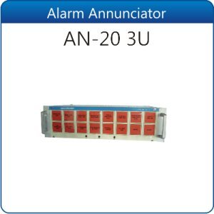
Figure 3.1: Front view of the Electronet Alarm Annunciator AN-20 3U. The image displays the annunciator unit with multiple red indicator windows, typically used for alarm indication, arranged in rows. The unit appears to be designed for rack mounting.
3.1. Key Components
- Indicator Windows: Super bright LEDs for visual alarm indication.
- Input Terminals: Connections for potential-free contacts (NO/NC).
- Output Terminals: Relay change-over contact for external hooter.
- Communication Ports: RS-485 / RS-232 for data exchange and configuration.
- Power Input: Terminal for power supply connection.
4. Setup and Installation
Follow these steps for proper installation of the AN-20 3U annunciator:
- Mounting: The AN-20 3U is designed for 19-inch rack mounting. Secure the unit firmly within the rack using appropriate mounting hardware.
- Power Connection: Connect the appropriate power supply to the designated power input terminals. Ensure the voltage and current ratings match the annunciator's requirements.
- Input Wiring: Connect the potential-free contacts from your sensors or process points to the annunciator's input terminals. Refer to the wiring diagram for correct NO (Normally Open) or NC (Normally Closed) configurations for each channel.
- Output Wiring: Connect the external hooter or alarm device to the relay change-over contact output terminals. This output activates when an alarm condition is met.
- Communication Setup (Optional): If using RS-485 or RS-232 communication, connect the appropriate cables to the communication ports. Refer to the communication protocol documentation for software configuration.
- Initial Power-Up: Once all connections are secure, apply power to the unit. Observe the power indicator and ensure no immediate fault indications.
5. Operating Instructions
The AN-20 3U operates by monitoring the status of its input channels and indicating alarm conditions.
5.1. Alarm Indication
- When an alarm condition occurs on a monitored channel, the corresponding super bright LED window will illuminate.
- Simultaneously, the external hooter connected to the relay output will activate, providing an audible alarm.
5.2. Acknowledging Alarms
Specific buttons or communication commands are typically used to acknowledge alarms. Refer to the detailed operational manual or system integration guide for your specific configuration. Acknowledging an alarm usually silences the hooter while the LED remains illuminated until the fault condition is cleared.
5.3. Resetting Alarms
Once the fault condition that triggered the alarm is resolved, the corresponding LED indicator will extinguish. If the system requires manual reset, use the designated reset function (button or communication command) to clear the alarm state completely.
6. Maintenance
The Electronet AN-20 3U is designed for low maintenance. However, regular checks can ensure optimal performance and longevity.
- Cleaning: Periodically clean the front panel and indicator windows with a soft, dry cloth. Do not use abrasive cleaners or solvents.
- Connection Checks: Annually inspect all wiring connections for tightness and signs of corrosion. Re-tighten if necessary.
- Functional Test: Periodically test the alarm functionality by simulating an alarm condition on each channel to ensure proper indication and hooter activation.
- Environmental Check: Ensure the operating environment remains within specified temperature and humidity ranges to prevent component degradation.
7. Troubleshooting
This section provides solutions to common issues you might encounter with the AN-20 3U.
| Problem | Possible Cause | Solution |
|---|---|---|
| No power indication | No power supply; faulty power cable; internal fuse blown. | Check power source and cable. Verify fuse. If problem persists, contact support. |
| Alarm LED not illuminating | Faulty input wiring; sensor issue; LED failure. | Verify input wiring and sensor functionality. Test the channel. |
| Hooter not activating | Hooter faulty; output wiring issue; relay failure. | Check hooter connection and functionality. Verify output wiring. |
| Communication error | Incorrect port settings; faulty cable; software issue. | Verify communication settings (baud rate, parity). Check cable integrity. Consult software manual. |
8. Specifications
| Parameter | Detail |
|---|---|
| Brand | Electronet |
| Model | AN-20 3U |
| Item Part Number | Electonet-46 |
| Design | Microprocessor based |
| Channels | Min 16 & Max 48 |
| Input Type | Potential free contacts (NO / NC) |
| Output Type | Relay change-over contact for external hooter |
| Indication | Super bright LEDs for window indication |
| Input Circuit | Optically isolated |
| Communication Ports | RS-485 / RS-232 |
| Mounting | 19-inch rack mounting |
| First Available Date | 15 July 2016 |
9. Warranty and Support
For warranty information and technical support, please contact Electronet customer service. Keep your purchase receipt and product model number (AN-20 3U) readily available when seeking assistance.
Electronet is committed to providing reliable products and support. For detailed warranty terms and conditions, please refer to the documentation provided with your purchase or visit the official Electronet website.
Documents and downloads
Ask a question about this manual
Ask about setup, troubleshooting, compatibility, parts, safety, or missing instructions. Manuals+ will review the question and use this page’s manual context to help answer it.