1. Introduction
The KBM01 Bridge Rectifier is an electronic component designed to convert alternating current (AC) into direct current (DC). It is commonly used in power supplies to provide a stable DC voltage from an AC source. This manual provides essential information for the safe and effective use of the KBM01 Bridge Rectifier, including installation, operation, and technical specifications.
2. Safety Information
Always observe the following safety precautions when handling and installing the KBM01 Bridge Rectifier:
- Electrical Hazard: This component deals with electrical current. Ensure all power sources are disconnected before installation or maintenance to prevent electric shock.
- Proper Handling: Handle the component by its body, avoiding excessive force on the leads. Electrostatic discharge (ESD) precautions should be observed.
- Heat Dissipation: Bridge rectifiers can generate heat during operation. Ensure adequate ventilation or heat sinking is provided as per application requirements to prevent overheating.
- Polarity: Pay close attention to the polarity markings on the component and the circuit board to ensure correct installation. Incorrect polarity can damage the component and other circuit elements.
- Professional Installation: If you are not familiar with electronic circuit assembly, seek assistance from a qualified professional.
3. Setup and Installation
The KBM01 Bridge Rectifier is designed for through-hole mounting. Follow these steps for proper installation:
- Identify Pins: The KBM01 typically has four pins: two for AC input (marked with a wavy line or 'AC') and two for DC output (marked with '+' for positive and '-' for negative). Refer to the component's datasheet for exact pinout.
- Prepare Circuit Board: Ensure the circuit board has appropriately sized holes for the rectifier's leads.
- Insert Component: Carefully insert the leads of the KBM01 into the corresponding holes on the circuit board, ensuring correct orientation and polarity.
- Solder Connections: Solder the leads to the circuit board using appropriate soldering techniques. Ensure strong, clean solder joints. Avoid excessive heat that could damage the component.
- Verify Installation: Visually inspect the solder joints and component orientation to confirm correct installation before applying power.
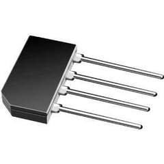
An image showing the KBM01 Bridge Rectifier, a small black rectangular electronic component with four metallic leads extending from one side, typically used for converting alternating current (AC) to direct current (DC).
4. Operating Principles
The KBM01 Bridge Rectifier contains four diodes arranged in a bridge configuration. When an AC voltage is applied to the AC input terminals, the diodes conduct in such a way that the output current always flows in the same direction, producing a pulsating DC voltage at the output terminals. This pulsating DC can then be smoothed by a filter capacitor to produce a more stable DC voltage for electronic circuits.
The rectifier is designed to handle specific voltage and current ratings. Exceeding these ratings can lead to component failure. Always operate the rectifier within its specified limits.
5. Maintenance
The KBM01 Bridge Rectifier is a passive electronic component and generally requires no routine maintenance. However, periodic inspection of the surrounding circuit and connections is recommended, especially in applications where the component is subjected to high temperatures or vibrations.
- Visual Inspection: Check for any signs of physical damage, discoloration (indicating overheating), or loose solder joints.
- Environmental Conditions: Ensure the operating environment remains within the specified temperature and humidity ranges.
- Dust and Debris: Keep the component and surrounding circuit free from dust and debris, which can impede heat dissipation.
6. Troubleshooting
If the circuit incorporating the KBM01 Bridge Rectifier is not functioning as expected, consider the following troubleshooting steps:
- No DC Output:
- Verify AC input voltage is present and within the rectifier's specifications.
- Check for correct polarity and connections of the rectifier.
- Inspect solder joints for cold joints or bridges.
- Test the rectifier using a multimeter (diode test mode) to check for open or shorted diodes.
- Overheating:
- Ensure the load current does not exceed the rectifier's maximum forward current rating.
- Verify adequate heat sinking or ventilation is provided.
- Check for short circuits in the load that could draw excessive current.
- Incorrect DC Voltage:
- Confirm the AC input voltage is correct.
- Check the filter capacitor (if used) for proper value and functionality.
7. Specifications
The following are general specifications for the KBM01 Bridge Rectifier. For detailed electrical characteristics, refer to the manufacturer's official datasheet.
| Parameter | Value |
|---|---|
| Model Number | KBM01 |
| Type | Bridge Rectifier |
| Manufacturer | G.I. |
| Package Type | DIP (Dual In-line Package) or similar through-hole |
| Maximum Reverse Voltage (VRRM) | Typically 100V (Note: Varies by specific KBM01 variant, consult datasheet) |
| Maximum Forward Current (IF(AV)) | Typically 1.0A (Note: Varies by specific KBM01 variant, consult datasheet) |
| Operating Temperature Range | Typically -55°C to +150°C (Note: Varies by specific KBM01 variant, consult datasheet) |
Note: The exact electrical specifications for voltage and current ratings can vary slightly between manufacturers for the KBM01 series. Always refer to the specific datasheet provided by the component's manufacturer for precise values relevant to your purchased part.
8. Warranty and Support
Information regarding specific warranty terms or direct technical support for the KBM01 Bridge Rectifier is not provided in this manual. For warranty claims, technical assistance, or to obtain the detailed datasheet for your specific component, please contact the original seller or the manufacturer, G.I., directly. Their contact information can typically be found on their official website or the product packaging.
For general electronics knowledge and community support, you may find resources on forums like EEVblog Forum or Electronics Stack Exchange.