1. Introduction
This manual provides essential information for the safe and efficient operation of your Cotek SP-3000-112 High Frequency Pure Sine Wave Inverter. This device converts 12V DC power from batteries into 120V AC power, suitable for a wide range of electronic appliances. Please read this manual thoroughly before installation and use, and retain it for future reference.
2. Safety Information
Failure to follow these safety instructions may result in electric shock, fire, serious injury, or death. Always exercise caution when working with electrical equipment.
- Read All Instructions: Before operating the inverter, read all instructions and cautionary markings on the inverter, the batteries, and all appropriate sections of this manual.
- Qualified Personnel: Installation and servicing should be performed by qualified personnel familiar with batteries and inverters.
- Ventilation: Ensure adequate ventilation around the inverter. Do not install in a zero-clearance compartment.
- Avoid Water: Do not expose the inverter to rain, snow, spray, or bilge water.
- Proper Grounding: The inverter must be properly grounded.
- Battery Safety: Work near lead-acid batteries is dangerous. Batteries generate explosive gases during normal operation. Ensure proper ventilation and wear appropriate personal protective equipment.
- Disconnect Power: Always disconnect the battery supply before performing any maintenance or troubleshooting.
- Correct Voltage: Ensure the DC input voltage matches the inverter's specifications (12VDC for this model).


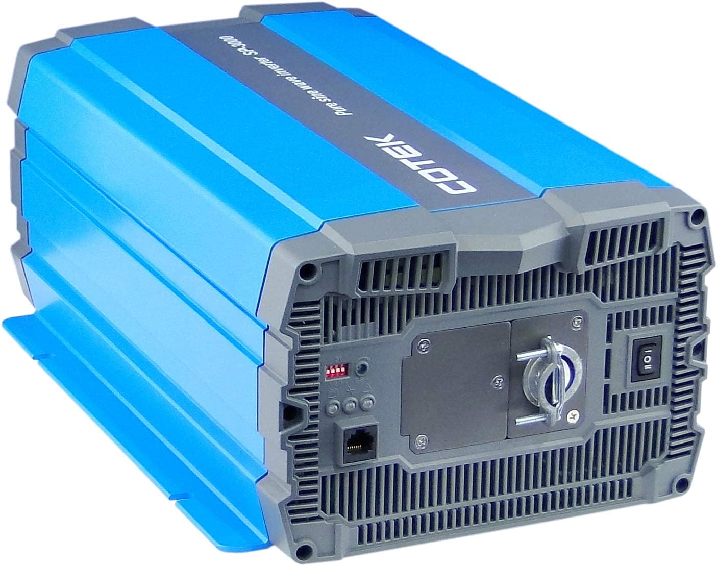
3. Product Overview
3.1 Key Features
- Pure sine wave output for sensitive electronics.
- Power ON / OFF remote control capability (Green Terminal).
- Input & output fully isolated for enhanced safety.
- Temperature & load controlled cooling fan for optimal performance.
- User-friendly interface with 3-color LED status indicators.
- Multiple protection features: Reverse Polarity (Fuse), Under Voltage / Over Voltage, Output Protection (Short Circuit / Overload / Over Temperature).
- E-13 / UL / CE / FCC approved.
3.2 Inverter Components

4. Setup and Installation
Proper installation is crucial for the safe and efficient operation of your inverter. Refer to local electrical codes and standards.
4.1 Placement
- Install the inverter in a dry, well-ventilated area, away from direct sunlight, heat sources, and flammable materials.
- Ensure sufficient clearance around the inverter for proper airflow, especially around the cooling fan vents.
- Mount the inverter securely on a stable, non-combustible surface.
- Avoid areas where dust, moisture, or corrosive fumes are present.
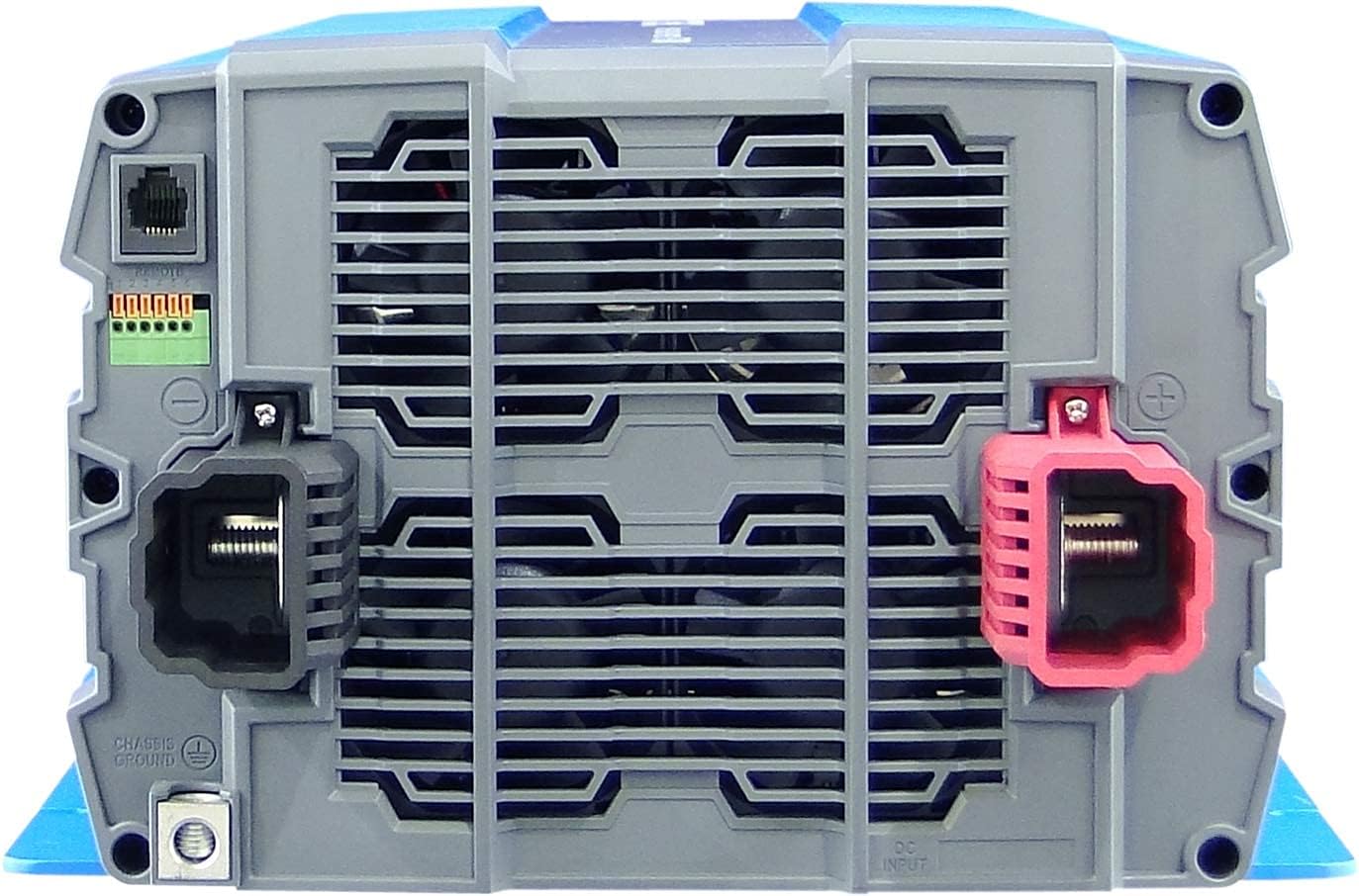
4.2 Wiring
All wiring must comply with applicable electrical codes and be performed by a qualified electrician.
- Grounding: Connect the inverter's chassis ground terminal to a reliable earth ground using appropriate gauge wire.
- DC Input Connection:
- Ensure the battery bank voltage is 12VDC.
- Use appropriately sized cables for the DC input to minimize voltage drop and ensure safety. Refer to cable sizing charts based on current and distance.
- Connect the positive (+) terminal of the battery bank to the red (+) terminal on the inverter.
- Connect the negative (-) terminal of the battery bank to the black (-) terminal on the inverter.
- Install a DC-rated fuse or circuit breaker between the battery bank and the inverter's positive terminal, as close to the battery as possible.
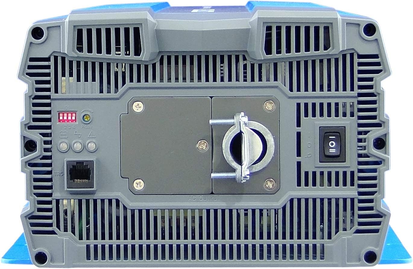
- AC Output Connection:
- Connect your AC loads to the hardwire AC output terminal block.
- Ensure the total load does not exceed the inverter's continuous power rating (3000W).
- Remote Control (Optional): Connect the remote control unit to the RJ45 port or use the green terminal for external ON/OFF control if desired.
5. Operating Instructions
5.1 Powering On/Off
- To Power On: Ensure all DC and AC connections are secure. Flip the main power switch on the inverter's rear panel to the 'ON' position. The Power LED indicator should illuminate.
- To Power Off: Disconnect all AC loads from the inverter. Flip the main power switch to the 'OFF' position.
5.2 LED Indicators
The inverter features 3-color LED status indicators on the control panel (refer to Figure 4) to provide operational feedback:
- Green LED: Indicates normal operation and power output.
- Yellow LED: Indicates a warning condition, such as low battery voltage or high temperature. The inverter may continue to operate but requires attention.
- Red LED: Indicates a fault condition, such as overload, short circuit, or severe over/under voltage. The inverter will shut down to protect itself and connected devices.
5.3 DIP Switch Settings
The DIP switches on the control panel allow for customization of certain inverter parameters, such as output voltage, frequency, and power saving mode. Refer to the detailed specifications table (Figure 5) or the product datasheet for specific configurations. Always adjust DIP switches when the inverter is powered off.
6. Maintenance
Regular maintenance ensures the longevity and reliable operation of your inverter.
- Cleaning: Periodically clean the exterior of the inverter with a dry cloth. Ensure ventilation openings are free from dust and debris. Do not use liquid cleaners.
- Connections: Regularly check all electrical connections (DC input, AC output, ground) for tightness and corrosion. Loose connections can cause overheating and poor performance.
- Battery Inspection: Inspect batteries for signs of damage, corrosion, or electrolyte leakage. Ensure battery terminals are clean and tight.
- Environment: Verify that the operating environment remains within the specified temperature and humidity ranges.
7. Troubleshooting
This section provides solutions to common issues you might encounter. If the problem persists, contact customer support.
| Problem | Possible Cause | Solution |
|---|---|---|
| Inverter does not turn on. | No DC input power; Loose battery connections; Blown DC fuse/breaker; Inverter switch OFF. | Check battery voltage; Tighten connections; Replace fuse/reset breaker; Turn inverter switch ON. |
| No AC output. | Overload; Short circuit; Over-temperature shutdown; Low/High DC input voltage. | Reduce AC load; Check for short circuits in wiring/appliances; Allow inverter to cool; Check battery voltage. |
| Yellow LED illuminated. | Low battery voltage warning; High temperature warning. | Recharge batteries; Ensure adequate ventilation, reduce load. |
| Red LED illuminated / Inverter shut down. | Overload; Short circuit; Over-temperature; Under/Over voltage. | Identify and correct the fault (e.g., reduce load, fix short, allow cooling, check battery voltage), then restart the inverter. |
| Cooling fan runs constantly or loudly. | High internal temperature due to heavy load or poor ventilation. | Reduce load; Improve ventilation around the inverter. |
8. Specifications
The following table outlines the technical specifications for the Cotek SP-3000 Series Pure Sine Wave Inverter, specifically for the SP-3000-112 model.

| Category | Parameter | SP-3000-112 |
|---|---|---|
| Output | AC Voltage | 100 / 110 / 115 / 120VAC ±5% |
| Rated Power | 3000W | |
| Surge Power (1 Sec.) | 6000W | |
| Maximum Output Power (1 Min) | 3450W | |
| Output Waveform | Pure Sine Wave (THD<3%) | |
| Frequency | 50 / 60 Hz ±0.5% | |
| Input | DC Voltage | 12VDC |
| Voltage Range | 10.5 ~ 16.5VDC | |
| No Load Current | <3.0A@12VDC | |
| Power Saving Mode | <0.4A@12VDC | |
| Efficiency (Max.) | 90% | |
| Protection | Input Under - Voltage Protection | 10.5 ±0.3VDC |
| Input Under - Voltage Alarm | 11.0 ±0.3VDC | |
| Input Under - Voltage Recovery | 12.0 ±0.3VDC | |
| Input Over - Voltage Protection | 16.5 ±0.3VDC | |
| Input Over - Voltage Recovery | 14.5 ±0.3VDC | |
| Output Overload | Shutdown output voltage, restart to recover | |
| Output Short | Shutdown output voltage, restart to recover | |
| Environment | Operating Temp. | -20°C ~ +40°C |
| Storage Temp. & Humidity | -30°C ~ +70°C, 10 ~ 95% RH | |
| General | Dimensions (W x H x D) | 442 x 214 x 102 mm (17.4 x 8.4 x 4.0 inches) |
| Weight | 8.2kg (18.1 lbs) | |
| Cooling | Temperature & load controlled cooling fan |

9. Warranty and Support
9.1 Warranty Information
The Cotek SP-3000-112 Pure Sine Wave Inverter comes with a 2-Year Manufacturer Warranty. This warranty covers defects in materials and workmanship under normal use. Please retain your proof of purchase for warranty claims.
9.2 Customer Support
For technical assistance, troubleshooting beyond this manual, or warranty inquiries, please contact Cotek customer support through their official website or your point of purchase. Provide your model number (SP-3000-112) and a detailed description of the issue to expedite service.


