1. Product Overview
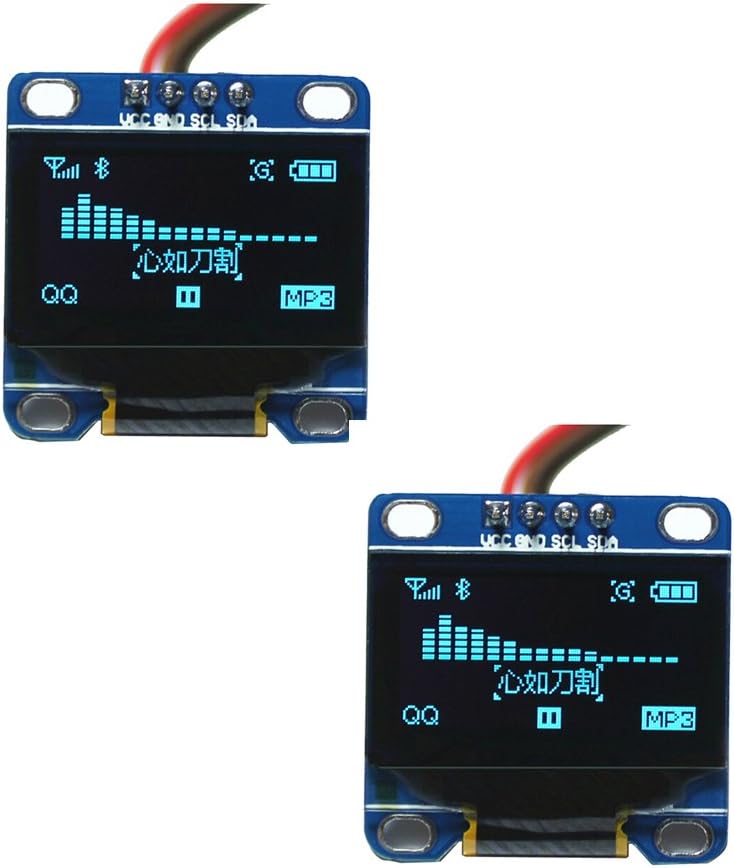
The DIYmall 0.96 Inch Blue OLED Module is a compact, self-illuminating display featuring 128x64 pixels. It utilizes an I2C/IIC serial interface, requiring only two I/O pins for communication. This module is designed for integration with various microcontroller platforms, including Arduino, Micro:bit, 51 series, MSP430 series, and STIM32/2/SCR chips. Its blue display offers a wide viewing angle of over 160 degrees and operates with low power consumption.
2. Specifications
| Feature | Description |
|---|---|
| Size | 0.96 Inch |
| Color | Blue |
| Resolution | 128x64 pixels |
| Viewing Angle | Greater than 160 degrees |
| Supported Platforms | Arduino, 51 series, MSP430 series, STIM32/2, SCR chips, Micro:bit |
| Power Consumption | 0.04W (normal operation) |
| Voltage Support | 3.3V-5V DC |
| Working Temperature | -30 to 80 degrees Celsius |
| Dimensions (Volume) | 27mm x 27mm x 4.1mm |
| Driver IC | SSD1306 |
| Communication Interface | IIC (I2C), 2 I/O ports required |
| Font Handling | Software-based word modulo (no built-in font) |
| Backlight | OLED self-illuminating, no separate backlight required |
| Product Dimensions (L x W x H) | 1.18 x 1.97 x 1.18 inches |
| Item Weight | 0.353 ounces |
| Model Number | FZ1112 |


3. Setup
This section outlines the basic steps for connecting and preparing your DIYmall 0.96 Inch Blue OLED Module for use with a microcontroller.
3.1 Wiring Connections (Arduino Example)
The OLED module communicates via I2C (also known as IIC), requiring four connections:
- VCC: Power supply (3.3V-5V)
- GND: Ground
- SCL: Serial Clock Line (I2C Clock)
- SDA: Serial Data Line (I2C Data)
For an Arduino UNO, typical connections are:
- OLED VCC to Arduino 5V (red wire)
- OLED GND to Arduino GND (black wire)
- OLED SCL to Arduino A5 (white wire)
- OLED SDA to Arduino A4 (yellow wire)

3.2 I2C Address Configuration
The I2C address of the module can be changed if necessary. Refer to the product's third picture for details on modifying the IIC address by adjusting a resistor.

3.3 Library Installation (Arduino IDE)
To use the OLED module with Arduino, you will need to install the appropriate libraries. The Adafruit SSD1306 library is commonly used. Ensure you also have the Adafruit GFX library installed as it is a dependency.
Steps:
- Open the Arduino IDE.
- Go to Sketch > Include Library > Manage Libraries...
- Search for "SSD1306" and install the "Adafruit SSD1306" library.
- Search for "GFX" and install the "Adafruit GFX Library".
- For clock functionality with ESP32, you may also need the "RTClib" library.
For detailed instructions on library installation and code examples, refer to the following video:
4. Operating
Once the module is wired and libraries are installed, you can upload example code to test its functionality and begin your projects.
4.1 Basic Display Functionality
The Adafruit SSD1306 library includes examples that demonstrate various display functions such as drawing shapes, text, and bitmaps. These examples are a good starting point to verify your setup.

4.2 Using with ESP32 and Clock Module
The OLED module can be combined with an ESP32 development board and a DS3231 Real-Time Clock (RTC) module to create projects requiring time display. Ensure correct wiring between the ESP32, RTC, and OLED module.
Connection Diagram (ESP32, DS3231, OLED):
- ESP-32 3V3/5V to DS3231 VCC and OLED VCC
- ESP-32 GND to DS3231 GND and OLED GND
- ESP-32 D21 to DS3231 SDA and OLED SDA
- ESP-32 D22 to DS3231 SCL and OLED SCL
Refer to the following video for a visual guide on connecting and using the OLED module with an ESP32 and clock module:
5. Maintenance
The DIYmall 0.96 Inch Blue OLED Module is a robust component, but proper handling and care will ensure its longevity and optimal performance.
- Handling: Avoid applying excessive pressure to the display surface. Handle the module by its edges to prevent damage to the screen or circuit board.
- Cleaning: If necessary, gently clean the display surface with a soft, dry, lint-free cloth. Do not use abrasive cleaners or solvents.
- Storage: Store the module in a dry, anti-static environment, away from direct sunlight and extreme temperatures.
- Power Supply: Always ensure your power supply voltage is within the specified 3.3V-5V DC range to prevent damage.
6. Troubleshooting
If you encounter issues with your OLED module, consider the following troubleshooting steps:
- Display Not Lighting Up:
- Verify all wiring connections (VCC, GND, SDA, SCL) are correct and secure.
- Ensure the power supply voltage is within the 3.3V-5V range.
- Check if the microcontroller is powered on and running the code.
- Incorrect Display Output or No Output:
- I2C Address: The default I2C address for the SSD1306 is often 0x3C or 0x3D. If your code uses 0x3D and the display is not working, try changing it to 0x3C in your code (e.g.,
display.begin(SSD1306_SWITCHCAPVCC, 0x3C);). Refer to Image 3.2 for physical address modification if needed. - Library Issues: Confirm that the Adafruit SSD1306 and Adafruit GFX libraries are correctly installed and updated in your Arduino IDE.
- Code Errors: Review your code for any syntax errors or logical issues. Use the Arduino IDE's serial monitor to check for debug messages.
- Pin Assignments: Double-check that the SDA and SCL pins in your code match the physical pins you've connected on your microcontroller.
- I2C Address: The default I2C address for the SSD1306 is often 0x3C or 0x3D. If your code uses 0x3D and the display is not working, try changing it to 0x3C in your code (e.g.,
- Flickering Display:
- Ensure stable power supply.
- Check for loose connections.
For further assistance, consult online forums and resources related to SSD1306 OLED displays and your specific microcontroller platform.
7. Warranty and Support
For warranty information or technical support regarding your DIYmall 0.96 Inch Blue OLED Module, please contact DIYmall directly through their official channels or the retailer from whom the product was purchased. Keep your proof of purchase for any warranty claims.

