1. Introduction
This manual provides essential information for the proper installation, operation, and maintenance of your Pwc Engine Neutral Safety Switch. Please read these instructions thoroughly before installation and retain for future reference. Adherence to these guidelines will ensure safe and reliable performance of the product.
2. Product Overview
The Pwc Engine Neutral Safety Switch is a high-quality, OEM-style replacement component designed to ensure the safe operation of your watercraft. It prevents engine starting unless the transmission is in neutral, enhancing safety for both the operator and the equipment. This switch is manufactured to meet or exceed OEM standards, providing reliable performance.
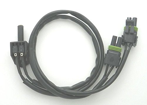
An image showing the Pwc Engine Neutral Safety Switch. It features a black plastic switch body with two pins, connected to a black wiring harness. The harness branches into two separate wires, each terminating in a black connector with a green seal, indicating a sealed connection type.
3. Compatibility
This Neutral Safety Switch is compatible with the following Yamaha models and OEM part numbers:
- OEM Part Numbers: WSM 004-109, GP1-U8090-00-00
- Compatible Yamaha Models:
- AR 210cc: 2003-2005
- Exciter 135cc SE: 1999
- Exciter 270cc TE: 1999
- LS 2000: 1999-2003
- LX 2000: 2002
- LX 210cc: 2003-2005
- SR 230cc: 2003-2005
- XR 1800cc: 2000-2001
4. Safety Information
WARNING: Always disconnect the battery before performing any electrical work on your watercraft to prevent electrical shock or damage to components.
CAUTION: Improper installation of a neutral safety switch can lead to unintended engine starting or failure to start, posing a safety risk. If you are unsure about any step, consult a qualified marine technician.
Ensure all connections are secure and properly sealed to prevent water intrusion, which can cause electrical shorts or corrosion.
5. Installation
Installation of the neutral safety switch typically involves replacing the existing switch. Follow these general steps:
- Preparation: Ensure the watercraft is on a stable surface and the engine is off. Disconnect the negative terminal of the battery.
- Locate Existing Switch: Identify the current neutral safety switch on your watercraft. Refer to your watercraft's service manual for the exact location.
- Disconnect Wiring: Carefully disconnect the electrical connectors from the old neutral safety switch. Note the orientation and connection points if necessary.
- Remove Old Switch: Unmount and remove the old neutral safety switch from its position.
- Install New Switch: Position the new Pwc Engine Neutral Safety Switch (Model PWC 004-109 A) in the same location as the old one. Secure it properly.
- Connect Wiring: Connect the electrical connectors of the new switch to the corresponding wiring harness. Ensure a firm and secure connection. The connectors are designed for a plug-in fit.
- Test Functionality: Reconnect the battery. Before starting the engine, verify that the engine will only crank when the transmission is in the neutral position. Attempt to start the engine in gear to confirm the safety switch prevents ignition.
- Final Check: Inspect all connections for security and ensure no wires are pinched or exposed.
6. Operation
The neutral safety switch is an automatic safety device. Its primary function is to prevent the engine from starting unless the transmission is in the neutral position. This ensures that the propeller is not engaged when the engine is started, reducing the risk of accidental movement or injury.
No user interaction is required for the operation of the switch itself, beyond ensuring the transmission is correctly placed in neutral before attempting to start the engine.
7. Maintenance
The Pwc Engine Neutral Safety Switch is designed for durability and minimal maintenance. However, periodic inspection is recommended:
- Visual Inspection: Annually inspect the switch and its wiring for any signs of wear, corrosion, or damage. Check for cracked insulation, loose connections, or physical damage to the switch body.
- Connection Integrity: Ensure all electrical connections remain clean and secure. Apply dielectric grease to connectors if operating in corrosive environments to prevent moisture ingress and corrosion.
- Functionality Test: Periodically test the switch's functionality by attempting to start the engine while the transmission is in a forward or reverse gear. The engine should not crank. If it does, the switch may be faulty and requires replacement.
8. Troubleshooting
If the engine fails to start or starts in gear, the neutral safety switch may be a contributing factor. Consider the following troubleshooting steps:
- Engine Does Not Crank in Neutral:
- Verify the transmission is fully engaged in neutral.
- Check all electrical connections to the neutral safety switch for looseness or corrosion.
- Inspect the wiring harness for any breaks or damage.
- Test the switch for continuity using a multimeter (refer to a service manual for specific testing procedures). A faulty switch may not complete the circuit in neutral.
- Engine Cranks/Starts in Gear:
- This indicates a failure of the neutral safety switch or its circuit. The switch is not preventing current flow when it should.
- Immediately cease operation and have the switch inspected and replaced by a qualified technician. Operating a watercraft with a bypassed or faulty neutral safety switch is extremely dangerous.
9. Specifications
| Feature | Specification |
|---|---|
| Brand | Pwc Engine |
| Model Number | PWC 004-109 A |
| OEM Cross-Reference | WSM 004-109, GP1-U8090-00-00 |
| Connector Type | Plug In |
| Specification Met | OEM Standards or Higher |
| Unit Count | 1.0 Count |
10. Warranty and Support
For warranty information or technical support regarding your Pwc Engine Neutral Safety Switch, please contact Pwc Engine directly or refer to their official website. Ensure you have your product model number (PWC 004-109 A) and purchase details available when seeking assistance.


