
ABB ACS355-03E-15A6-4
ABB Inverter ACS355-03E-15A6-4 User Manual
Model: ACS355-03E-15A6-4
1. Introduction
This manual provides essential information for the safe and efficient installation, operation, and maintenance of the ABB ACS355-03E-15A6-4 Inverter. Please read this manual thoroughly before attempting any procedures to ensure proper handling and to prevent personal injury or damage to the equipment.
The ABB ACS355-03E-15A6-4 is a versatile variable frequency drive designed for a wide range of industrial applications, offering precise motor control and energy efficiency.
2. Safety Information
Always observe the following safety precautions when working with the inverter:
- Electrical Hazard: This equipment operates with high voltages. Only qualified personnel should perform installation, maintenance, and troubleshooting.
- Disconnect Power: Always disconnect all power sources before working on the inverter or connected equipment. Wait for capacitors to discharge completely.
- Grounding: Ensure the inverter is properly grounded according to local electrical codes.
- Personal Protective Equipment (PPE): Use appropriate PPE, including safety glasses and insulated gloves, when handling the inverter.
- Environmental Conditions: Do not expose the inverter to moisture, dust, or extreme temperatures beyond its specified operating range.
⚠ WARNING: Failure to follow these safety instructions can result in serious injury or death.
3. Setup and Installation
Proper installation is crucial for the inverter's performance and longevity. Follow these general guidelines:
3.1. Mounting
Mount the inverter vertically on a flat, non-flammable surface, ensuring adequate clearance for ventilation. Avoid mounting in direct sunlight or near heat sources. Use appropriate fasteners for secure installation.
3.2. Wiring Connections
Refer to the wiring diagram and terminal labels on the inverter for correct connections. Use appropriately sized cables and ensure all connections are tight.
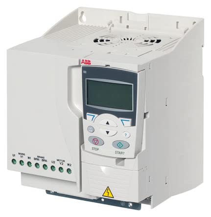
Figure 3.2.1: Front view of the ABB ACS355-03E-15A6-4 Inverter. The image displays the compact design of the inverter, featuring a prominent control panel with an LCD screen and navigation buttons (STOP, START). Below the control panel, a yellow warning triangle symbol is visible. On the left side, a green terminal block is shown with labels for power input (MAINS U1, V1, W1), brake connections (BRK-BRK), and motor output (MOTOR U2, V2, W2). The top of the unit includes ventilation grilles.
- Mains Input (U1, V1, W1): Connect the incoming AC power supply to these terminals.
- Brake Resistor (BRK-BRK): If a braking resistor is used, connect it to these terminals.
- Motor Output (U2, V2, W2): Connect the motor leads to these terminals.
- Grounding: Ensure the protective earth (PE) terminal is properly connected to ground.
3.3. Initial Power-Up
After all connections are secure, apply power to the inverter. The control panel display should illuminate. Follow the initial setup wizard (if applicable) or refer to the operating section for basic parameter configuration.
4. Operating Instructions
The inverter's control panel allows for easy operation and monitoring.
4.1. Control Panel Overview
The control panel features an LCD display, navigation buttons (up, down, left, right, enter), a STOP button, and a START button. These allow you to navigate menus, view parameters, and control motor operation.
- START Button: Initiates motor operation.
- STOP Button: Halts motor operation.
- Navigation Buttons: Used to scroll through menus and adjust parameter values.
- LCD Display: Shows operational status, parameter values, and error messages.
4.2. Basic Operation
- Ensure the motor and all connections are secure.
- Press the STOP button to ensure the inverter is in a stopped state.
- Set the desired speed or frequency using the control panel's navigation buttons.
- Press the START button to begin motor operation.
- Monitor the display for operational feedback.
4.3. Parameter Settings
The inverter has numerous parameters that can be configured to optimize performance for specific applications. Refer to the detailed programming guide (not included in this general manual) for a complete list and explanation of all parameters.
5. Maintenance
Regular maintenance ensures the longevity and reliable operation of your ABB inverter.
- Cleaning: Periodically clean the inverter's exterior with a soft, dry cloth. Ensure ventilation openings are free from dust and debris. Do not use liquid cleaners.
- Fan Inspection: Check the cooling fan(s) for proper operation and cleanliness. Replace if noisy or not functioning correctly.
- Connection Checks: Annually inspect all electrical connections for tightness and signs of corrosion.
- Environmental Check: Ensure the operating environment remains within specified temperature and humidity limits.
⚠ CAUTION: Always disconnect power before performing any maintenance.
6. Troubleshooting
This section provides solutions to common issues you might encounter. For complex problems, contact ABB support.
| Problem | Possible Cause | Solution |
|---|---|---|
| Inverter does not power on. | No input power; Blown fuse; Loose connection. | Check power supply; Inspect fuses; Verify all wiring connections. |
| Motor does not run. | Inverter in STOP mode; Incorrect parameter settings; Motor fault. | Press START button; Check motor parameters; Inspect motor and wiring. |
| Overcurrent fault. | Motor overload; Short circuit in motor wiring; Incorrect acceleration time. | Reduce load; Check motor wiring; Increase acceleration time parameter. |
| Overvoltage fault. | High input voltage; Regenerative braking without resistor; Incorrect deceleration time. | Check input voltage; Install or check braking resistor; Increase deceleration time parameter. |
If an error code appears on the display, consult the full product manual for specific code definitions and troubleshooting steps.
7. Specifications
Key specifications for the ABB ACS355-03E-15A6-4 Inverter:
- Model: ACS355-03E-15A6-4
- Brand: ABB
- Type: Variable Frequency Drive (VFD) / Inverter
- Input Voltage: (Typical) 3-phase, 380-480V AC
- Output Power: (Typical) 7.5 kW / 10 HP
- Protection Class: (Typical) IP20
- Operating Temperature: (Typical) 0°C to +40°C (32°F to 104°F)
- Dimensions (approx.): (Typical) 200mm x 150mm x 180mm (H x W x D)
8. Warranty Information
The ABB ACS355-03E-15A6-4 Inverter comes with a One Year Warranty from the date of purchase. This warranty covers defects in materials and workmanship under normal use and service.
To claim warranty service, please retain your proof of purchase and contact your authorized ABB distributor or service center. The warranty does not cover damage caused by improper installation, misuse, unauthorized modifications, or natural disasters.
9. Support
For technical assistance, detailed product documentation, or service inquiries, please contact ABB customer support or visit the official ABB website.
ABB Official Website: www.abb.com
When contacting support, please have your inverter's model number (ACS355-03E-15A6-4) and serial number ready.
Related documentsACS355-03E-15A6-4


Ask a question about this manual
Ask about setup, troubleshooting, compatibility, parts, safety, or missing instructions. Manuals+ will review the question and use this page’s manual context to help answer it.