
1. Introduction
This manual provides detailed instructions for the installation, operation, maintenance, and troubleshooting of the DIGITEN G3/4" Water Flow Hall Sensor Switch, Model FL-608. This device is designed to accurately measure water flow rates in various applications, providing a pulse output signal proportional to the flow volume. Please read this manual thoroughly before using the product to ensure proper function and safety.
2. Safety Information
- Ensure all electrical connections are made correctly and are insulated to prevent short circuits or electric shock.
- Do not exceed the specified working voltage range (DC 5-18 V) or maximum current (15 mA).
- Verify that the water pressure in your system does not exceed 1.75 MPa (17.5 bar) to prevent damage to the sensor.
- Install the sensor in a location protected from direct exposure to extreme weather conditions unless specifically designed for such environments.
- Always disconnect power before performing any installation or maintenance.
3. Product Features
- Flow Range: 1 to 60 Liters per minute (L/min)
- Output Signal: Square Wave pulse signal
- Working Voltage: DC 5-18 V
- Maximum Current: 15 mA (at DC 5V)
- Load Capacity: Approximately 10 mA (at DC 5V)
- Operating Temperature: 0-80℃
- Operating Humidity: 35%-90% RH
- Allowable Compression: Water pressure below 1.75 MPa
- Insulation Resistance: >100M Ohm
- Storage Temperature: -25~80℃
- Storage Humidity: 25%-95% RH
- Material: Durable plastic body with G3/4" threaded connections
- Cable Length: 15 cm
- ROHS Compliant
4. Setup and Installation
Follow these steps for proper installation of your DIGITEN water flow sensor:
- Identify Flow Direction: Locate the arrow on the sensor body, which indicates the correct direction of water flow. Install the sensor so that water flows in this direction.
- Plumbing Connection: The sensor features G3/4" male threaded connections. Apply appropriate thread sealant (e.g., PTFE tape) to ensure a watertight seal. Connect the sensor inline with your water pipe system. Ensure connections are tight but do not overtighten to avoid damaging the plastic threads.
- Electrical Wiring: The sensor has a three-wire cable with a connector. The wiring is as follows:
- Red Wire: VCC (Positive power supply, DC 5-18V)
- Black Wire: GND (Ground)
- Yellow Wire: Signal Output (Pulse signal)
- Power On and Test: After all connections are secure, turn on the water supply and electrical power. Check for any leaks in the plumbing and verify that the sensor is outputting a signal when water flows.
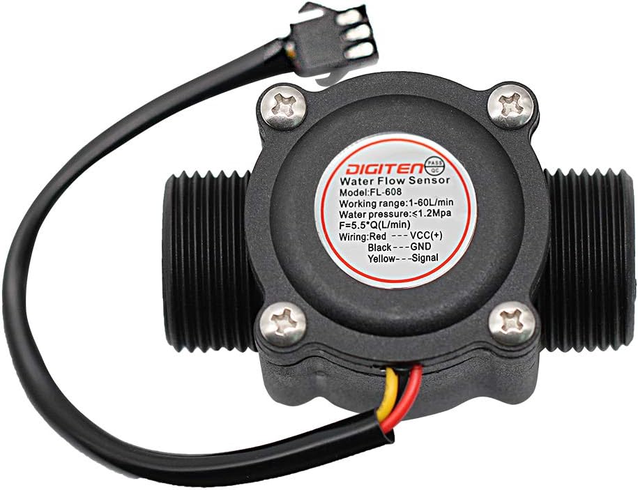
This image displays the DIGITEN G3/4 inch Water Flow Hall Sensor Switch. The main black plastic body features G3/4 inch threaded inlet and outlet ports. A label on the top of the sensor provides essential information including the model number (FL-608), working range (1-60 L/min), maximum water pressure (1.75 MPa), and wiring instructions (Red: VCC, Black: GND, Yellow: Signal). A three-wire cable (red, black, yellow) extends from the sensor, terminating in a connector.

This top-down view of the DIGITEN water flow sensor clearly shows an arrow indicating the recommended direction of water flow through the sensor. This ensures correct installation for accurate measurements.

A close-up view of the 3-pin connector attached to the wiring harness of the water flow sensor. This connector facilitates easy and secure electrical connection to a control system.
5. Operating Instructions
The DIGITEN FL-608 water flow sensor operates on the Hall effect principle. As water flows through the sensor, a rotor with magnets spins. The Hall effect sensor detects these rotations and generates a series of electrical pulses. The frequency of these pulses is directly proportional to the water flow rate.
Flow Rate Calculation
The relationship between the output frequency (F) and the flow rate (Q) for this sensor is given by the formula:
F = 5.5 * Q
Where:
- F is the frequency in Hz (pulses per second)
- Q is the flow rate in Liters per minute (L/min)
The sensor generates approximately 330 pulses per liter. To calculate the total volume of water that has passed through the sensor, you can count the total number of pulses and divide by 330.
6. Maintenance
- Regular Inspection: Periodically inspect the sensor and its connections for any signs of wear, damage, or leaks.
- Cleanliness: Ensure the area around the sensor is kept clean and free from debris that could interfere with its operation or connections.
- Avoid Freezing: In cold environments, ensure the sensor and connected pipes are protected from freezing, which can cause damage.
- Electrical Connections: Check electrical connections for corrosion or looseness and secure them as needed.
7. Troubleshooting
| Problem | Possible Cause | Solution |
|---|---|---|
| No pulse signal output | Incorrect wiring; No power; Sensor malfunction; No water flow. | Verify wiring (Red to VCC, Black to GND, Yellow to Signal). Check power supply. Ensure water is flowing through the sensor. Test with a known working sensor if possible. |
| Inaccurate flow readings | Incorrect flow direction; Air bubbles in the line; Sensor calibration issue; Debris inside sensor. | Ensure sensor is installed according to the flow direction arrow. Bleed air from the water line. Verify calculation formula. Inspect sensor for internal obstructions. |
| Water leakage at connections | Loose connections; Insufficient thread sealant; Damaged threads. | Tighten connections carefully. Reapply thread sealant. Inspect threads for damage and replace if necessary. |
| Signal 'chattering' or erratic pulses | Electrical interference; Sensor nearing end of life; Low flow rate causing unstable rotor movement. | Ensure proper shielding for signal wire. Consider replacing the sensor if it's old. Implement software filtering for low flow rates. |
| Thread incompatibility (e.g., NPT vs. BSP) | The sensor uses G3/4" (BSP) threads, which are not compatible with NPT threads without an adapter. | Use appropriate G3/4" fittings or acquire suitable adapters for your plumbing system. |
8. Specifications
| Specification | Value |
|---|---|
| Model Number | FL-608 |
| Flow Range | 1-60 L/min |
| Working Voltage Range | DC 5-18 V |
| Maximum Current | 15 mA (DC 5V) |
| Load Capacity | ~10 mA (DC 5V) |
| Operating Temperature | 0-80℃ |
| Operating Humidity | 35%-90% RH |
| Allowable Compression | Water pressure < 1.75 MPa |
| Insulation Resistance | >100M Ohm |
| Storage Temperature | -25~80℃ |
| Storage Humidity | 25%-95% RH |
| Output Waveform | Square Wave, pulse signal |
| Pulses per Liter | 330 pulses/liter |
| Connection Size | G3/4" (0.75 Inches) |
| Material | Stainless Steel (internal components), Plastic (housing) |
| Cable Length | 15 cm |
| Item Weight | 2.47 ounces |
9. Warranty and Support
DIGITEN provides a one-year warranty term for any product quality problems. If you encounter any issues with your FL-608 water flow sensor, please contact DIGITEN customer support for assistance. Our products are designed for ease of use and operation, with a focus on product longevity.
