
1. Introduction
This manual provides comprehensive instructions for the installation, operation, and maintenance of your American Volt Universal Dual Electric Radiator Cooling Fan Grounding Thermostat Relay Wiring Switch Kit. This kit is designed to activate up to two 12V electric cooling fans based on a pre-set liquid temperature, ensuring optimal engine cooling performance.
2. Safety Information
Always prioritize safety when working on automotive electrical systems. Failure to follow these guidelines may result in personal injury or damage to your vehicle.
- Disconnect the vehicle's battery before beginning any electrical work to prevent accidental short circuits or electrical shock.
- Ensure all connections are secure and properly insulated to prevent arcing or shorting.
- Wear appropriate personal protective equipment, including safety glasses and gloves.
- Allow the engine and cooling system to cool down completely before handling components, as they can be extremely hot.
- If you are unsure about any step, consult a qualified automotive technician.
3. Kit Contents
Please verify that all components listed below are present in your kit before beginning installation.

Overview of the Universal Dual Electric Radiator Cooling Fan Kit components, including the relay, wiring harness, fuse, temperature probe, and various connectors and ties.
- (1) - 3/8" NPT Ground Thermostat Switch: This brass probe measures liquid temperature.
- (1) - Wiring Harness: Pre-wired connections for the relay and fan.
- (1) - 40 Amp Relay: Controls the power to the electric fans.
- (1) - 30 Amp Fuse: Provides circuit protection.
- (1) - Large Ring Terminal: For main power connection.
- (3) - Small Ring Terminals: For various ground and signal connections.
- (2) - Butt Connectors: For splicing wires.
- (4) - 4'' Wire Ties: For securing wiring.
- (1) - Female Connector: For the thermostat switch.
- (4) - Sheet Metal Screws: For mounting components.
- (2) - Splice Connectors: For quick wire connections.
4. Specifications
| Feature | Specification |
|---|---|
| Operating Voltage | 12 Volts |
| Current Rating (Relay) | 30 Amps (Max 25-30 amp draw from fans) |
| Thermostat Turn-On Temperature | 160°F (71°C) |
| Thermostat Turn-Off Temperature | 145°F (63°C) |
| Probe Thread Size | 3/8" NPT |
| Probe Material | Brass |
| Contact Type | Normally Open |
| Product Dimensions | 2 x 2 x 2 inches (approximate) |
5. Setup and Installation
Follow these steps carefully for proper installation of your cooling fan kit. It is recommended to have a basic understanding of automotive electrical systems.
5.1. Prepare for Installation
- Ensure the engine is cool to the touch.
- Disconnect the negative terminal of your vehicle's battery.
- Identify a suitable location for mounting the relay, away from excessive heat and moisture.
5.2. Install the Temperature Probe

Close-up view of the 3/8" NPT brass temperature probe, designed to thread into a radiator, water outlet, or manifold.

Another perspective of the brass temperature probe, highlighting its electrical connection point.
- The 3/8" NPT brass probe typically threads into an existing port on the radiator, water outlet, or intake manifold. Ensure the chosen location measures liquid temperature only.
- Apply thread sealant to the probe threads before installation to prevent leaks.
- Carefully thread the probe into the port until snug. Do not overtighten.
- Connect the supplied female connector to the terminal on the temperature probe.
5.3. Mount the Relay and Fuse Holder
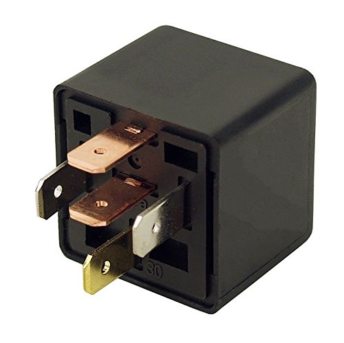
Isolated view of the 40 Amp relay, showing its pin configuration.

Detailed view of the 40 Amp relay and its associated wiring harness connectors.
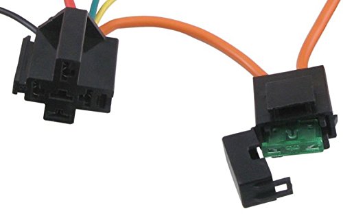
Close-up of the inline 30 Amp fuse holder, demonstrating where the fuse is inserted for circuit protection.
- Mount the 40 Amp relay securely using the provided sheet metal screws or wire ties in a location that is easily accessible but protected from direct elements.
- Mount the inline 30 Amp fuse holder in an easily accessible location near the battery or power source. Do not insert the fuse yet.
5.4. Wiring Connections
Refer to the wiring diagram provided with your kit for specific connections. General wiring principles are as follows:
- Power Input (Relay Pin 30): Connect the main power wire from the relay harness (typically red or orange) to a constant 12V power source, preferably directly to the positive battery terminal or a fused distribution block. Use the large ring terminal for this connection. This wire should pass through the 30 Amp fuse holder.
- Fan Power Output (Relay Pin 87): Connect the fan power output wire from the relay harness (typically blue or yellow) to the positive terminal of your electric cooling fan(s). If connecting two fans, ensure the wiring can handle the combined current draw.
- Relay Ground (Relay Pin 85): Connect the relay ground wire (typically black) to a good chassis ground point. Use a small ring terminal for this connection.
- Thermostat Signal (Relay Pin 86): Connect the thermostat signal wire from the relay harness (typically green or white) to the female connector that is attached to the 3/8" NPT temperature probe. The temperature probe itself will provide the ground signal to activate the relay when the set temperature is reached.
- Fan Ground: Ensure your electric cooling fan(s) have a separate, secure ground connection to the vehicle chassis.
5.5. Final Steps
- Secure all wiring using the provided wire ties, ensuring wires are away from moving parts, sharp edges, and excessive heat.
- Insert the 30 Amp fuse into the inline fuse holder.
- Reconnect the negative terminal of your vehicle's battery.
6. Operating Instructions
The American Volt cooling fan kit operates automatically based on the liquid temperature detected by the 3/8" NPT probe.
- When the liquid temperature reaches 160°F (71°C), the thermostat switch will close, providing a ground signal to the relay.
- The relay will then activate, supplying power to your electric cooling fan(s), causing them to turn on.
- The fan(s) will continue to run until the liquid temperature drops to 145°F (63°C). At this point, the thermostat switch will open, deactivating the relay and turning off the fan(s).
- This cycle will repeat as necessary to maintain optimal engine operating temperature.
7. Maintenance
Regular inspection of your cooling fan kit can help ensure its longevity and reliable operation.
- Periodically check all electrical connections for tightness and corrosion. Clean any corroded terminals.
- Inspect the wiring for any signs of fraying, cracking, or heat damage. Replace damaged wires immediately.
- Verify the fuse is intact. If it blows repeatedly, investigate the cause of the overcurrent.
- Ensure the temperature probe is securely threaded and not leaking coolant.
8. Troubleshooting
If your cooling fan kit is not operating as expected, refer to the following troubleshooting guide:
8.1. Fan Does Not Turn On
- Check Fuse: Inspect the 30 Amp fuse in the inline holder. Replace if blown.
- Verify Power: Use a multimeter to confirm 12V power is reaching Relay Pin 30.
- Check Grounds: Ensure all ground connections (Relay Pin 85, fan ground) are secure and free of corrosion.
- Test Thermostat Probe: With the engine hot (above 160°F), check for continuity between the probe terminal and the probe body. If no continuity, the probe may be faulty.
- Test Relay: You can test the relay by applying 12V to Pin 30 and Pin 86, and ground to Pin 85. You should hear an audible click, and there should be continuity between Pin 30 and Pin 87.
- Check Fan: Ensure the electric fan itself is operational by temporarily connecting it directly to a 12V power source.
8.2. Fan Runs Continuously
- Check Thermostat Probe: If the engine is cool (below 145°F) but the fan is running, the thermostat probe may be stuck in the closed position (shorted). Disconnect the wire from the probe; if the fan turns off, the probe is likely faulty.
- Check Relay: The relay may be stuck in the closed position. Replace the relay if disconnecting the thermostat probe wire does not turn off the fan.
- Wiring Short: Inspect the wiring for any shorts to ground on the thermostat signal wire (Relay Pin 86).
9. Warranty and Support
American Volt products are manufactured to high standards. For specific warranty information or technical support, please refer to the documentation included with your purchase or visit the official American Volt website. Keep your proof of purchase for warranty claims.
For further assistance, you may contact American Volt customer service through their official channels.