
Introduction
This manual provides detailed instructions for the installation, operation, and maintenance of your AUDIOTEK AT-850.5 5-Channel Class AB Car Amplifier. Please read this manual thoroughly before attempting installation or operation to ensure proper use and to prevent damage to the unit or your vehicle's electrical system.
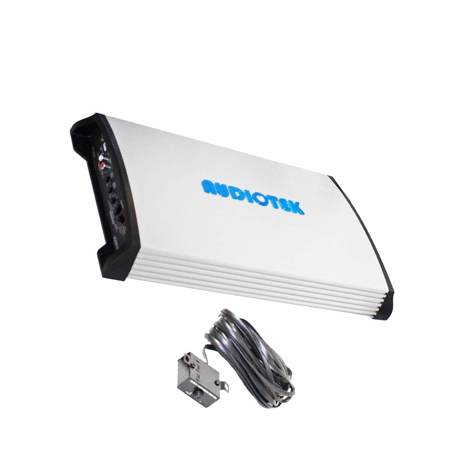
Image: The AUDIOTEK AT-850.5 5-Channel Class AB Car Amplifier. This image shows the overall design of the amplifier.
Safety Information
Always observe the following safety precautions during installation and operation:
- Disconnect the vehicle's negative battery terminal before starting any electrical work.
- Ensure all wiring is properly insulated to prevent short circuits.
- Mount the amplifier securely to prevent it from becoming a projectile in an accident.
- Avoid mounting the amplifier in areas exposed to direct sunlight, excessive heat, or moisture.
- Use appropriate gauge wiring for power and ground connections as specified in the installation section.
- If you are unsure about any part of the installation, consult a professional car audio installer.
Features
The AUDIOTEK AT-850.5 amplifier includes the following key features:
- 5-Channel Class A/B Operation: Provides efficient and high-quality audio output.
- 2 Ohm Stable: Capable of driving speakers with 2-ohm impedance for increased power output.
- Bridgeable MOSFET Amplifier: Allows for flexible configuration, including bridging channels for higher power to subwoofers.
- Continuously Variable Low Pass Crossover: Adjustable frequency control for precise audio tuning.
- Remote Subwoofer Control: External wired control for convenient bass level adjustment.
- Heavy-Duty Aluminum Alloy Heat Sink: Designed for efficient heat dissipation to ensure stable performance.
- Nickel Plated RCA and Speaker Level Inputs: Ensures reliable signal transfer.
- MOSFET Pulse Width Modulated Power Supply: Provides stable and efficient power delivery.
- Thermal and Speaker Short Protection Circuitry: Safeguards the amplifier and speakers from damage.
- LED Power and Protection Indicators: Visual status indicators for easy monitoring.
Package Contents
Verify that all items are present in the package:
- AUDIOTEK AT-850.5 5-Channel Amplifier
- Remote Bass Level Control
- Remote Bass Control Cable
- Mounting Hardware (screws)
- User Manual (this document)

Image: The AUDIOTEK AT-850.5 amplifier shown with its included remote bass control and cable.
Setup and Installation
Mounting the Amplifier
Choose a suitable location for mounting the amplifier. Considerations include:
- Ventilation: Ensure adequate airflow around the amplifier for proper cooling. Avoid enclosed spaces.
- Protection: Mount in a location that protects the amplifier from moisture and physical damage.
- Accessibility: Allow access to controls and wiring for adjustments and maintenance.
- Secure Fastening: Use the provided mounting hardware to securely fasten the amplifier to a solid surface in the vehicle.
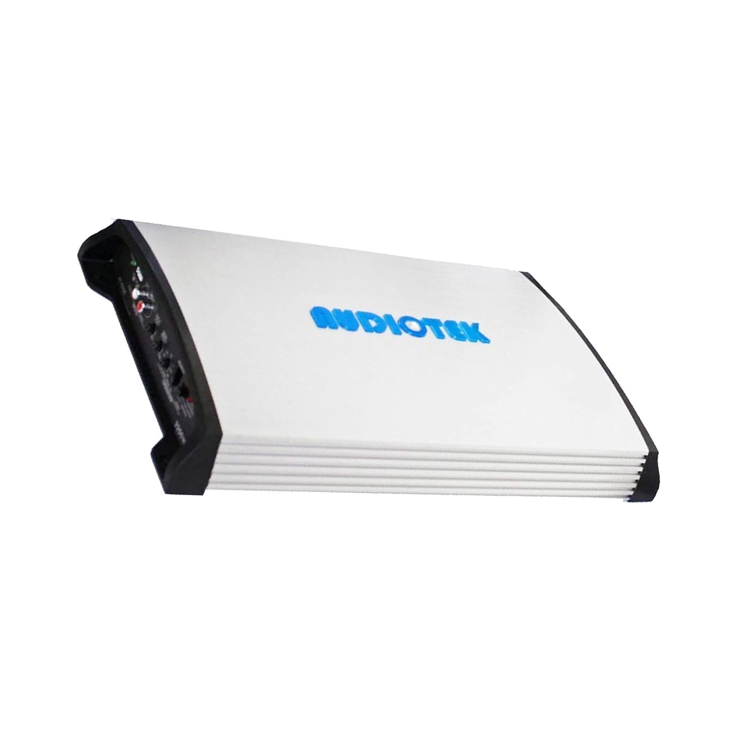
Image: Side view of the AUDIOTEK AT-850.5 amplifier, illustrating its heat sink design for proper ventilation.
Wiring Connections
Before making any connections, disconnect the negative terminal of your vehicle's battery.
- Power (BATT+): Connect a heavy-gauge power cable (e.g., 4 AWG or 8 AWG depending on total power draw) directly from the positive terminal of the vehicle's battery to the BATT+ terminal on the amplifier. Install an in-line fuse holder with an appropriate fuse (not included) within 18 inches (45 cm) of the battery.
- Ground (GND): Connect a heavy-gauge ground cable of the same size as the power cable from the GND terminal on the amplifier to a clean, unpainted metal surface on the vehicle's chassis. Ensure a good electrical connection.
- Remote Turn-On (REM): Connect a remote turn-on wire (typically 18 AWG) from the REM terminal on the amplifier to the remote output of your head unit. This wire turns the amplifier on and off with your car stereo.
- RCA Audio Inputs: Connect RCA cables from the pre-amp outputs of your head unit to the RCA INPUTs on the amplifier. Ensure correct channel matching (Left/Right, Front/Rear/Sub).
- Speaker Outputs: Connect your speakers to the SPEAKER OUTPUT terminals. Observe correct polarity (+ to + and - to -) for each speaker. Refer to the amplifier's specifications for minimum impedance per channel. For bridged operation, consult the specific bridging instructions for your amplifier model.
- Remote Bass Control: Connect the remote bass control module to the designated port on the amplifier using the provided cable.

Image: Close-up of the AUDIOTEK AT-850.5 amplifier's input and output panel, showing RCA inputs, speaker terminals, and control knobs.
Operating Instructions
Initial Setup and Adjustments
After all connections are made and verified, reconnect the vehicle's negative battery terminal. Turn on your head unit.
- Gain Control: Start with the gain control set to minimum. Play a familiar piece of music at about 75% of your head unit's maximum volume. Slowly increase the amplifier's gain control until you hear distortion, then back it off slightly. This sets the amplifier's input sensitivity to match your head unit's output.
- Crossover Settings:
- Low Pass Filter (LPF): If driving subwoofers, set the LPF to filter out high frequencies, typically between 80Hz and 120Hz.
- High Pass Filter (HPF): If driving full-range speakers, set the HPF to filter out low frequencies, typically between 60Hz and 100Hz, to protect them from damaging bass.
- Full Range: For full-range speakers that can handle all frequencies, you may choose to bypass the crossovers.
- Bass Boost: Use the bass boost feature sparingly. Excessive bass boost can lead to distortion and potential speaker damage. Start at 0dB and increase gradually if desired.
- Remote Bass Control: The remote bass control allows for convenient adjustment of the subwoofer level from the driver's seat.

Image: The remote bass control unit, used for adjusting subwoofer output levels.
Maintenance
The AUDIOTEK AT-850.5 amplifier requires minimal maintenance. Follow these guidelines:
- Cleaning: Periodically wipe the amplifier's exterior with a soft, dry cloth to remove dust. Do not use harsh chemicals or abrasive cleaners.
- Ventilation: Ensure that the heat sink fins remain clear of obstructions to allow for proper cooling.
- Connections: Occasionally check all wiring connections to ensure they are secure and free from corrosion.
Troubleshooting
If you experience issues with your amplifier, refer to the following common problems and solutions:
| Problem | Possible Cause / Solution |
|---|---|
| No Power / Amplifier does not turn on |
|
| No Sound Output |
|
| Distorted Sound |
|
| Amplifier Overheats / Goes into Protection Mode |
|
Specifications
Key specifications for the AUDIOTEK AT-850.5 amplifier:
| Feature | Detail |
|---|---|
| Model Number | AT-850.5 |
| Brand | AUDIOTEK |
| Number of Channels | 5 |
| Amplifier Class | Class A/B |
| Stable Impedance | 2 Ohm Stable |
| Dimensions (L x W x H) | 40.6 x 22.9 x 7.6 Centimeters (approx. 16 x 9 x 3 inches) |
| Item Weight | 4.54 kg (approx. 10 lbs) |
| Power Supply | MOSFET Pulse Width Modulated |
| Protection Circuitry | Thermal and Speaker Short Protection |
| Inputs | Nickel Plated RCA and Speaker Level Inputs |
| Crossover | Continuously Variable Low Pass Crossover |
| Remote Control | Remote Subwoofer Control |
Warranty and Support
For warranty information and technical support, please refer to the documentation provided with your purchase or contact AUDIOTEK customer service. Keep your proof of purchase for warranty claims.