
1. Introduction
The MPT-7210A Solar Charge Controller utilizes Maximum Power Point Tracking (MPPT) technology to efficiently manage solar panel output. This controller is designed to track the highest voltage and current (V-I) point of photovoltaic panels in real-time, optimizing power output for battery charging. It is a crucial component in solar photovoltaic systems, coordinating solar panels to charge various battery types.

Figure 1: Front view of the MPT-7210A Solar Charge Controller, showing the LCD display and control buttons.
2. Safety Information
Please adhere strictly to the wiring diagram provided in this manual. Ensure correct positive and negative connections for both input and output lines to prevent damage to the equipment. All electrical connections must be made with the power off. Failure to do so may result in equipment damage, personal injury, or property damage.
- Always disconnect power before making or breaking connections.
- Ensure proper ventilation around the controller.
- Do not expose the controller to water or excessive moisture.
- Consult a qualified electrician if you are unsure about any installation steps.
3. Key Features
- Input Voltage: DC12-60V
- Output Voltage: DC15V-90V (Continuously adjustable to accommodate 24V/36V/48V/72V battery packs)
- Output Current: 0-10A (Continuously adjustable via key settings)
- Output Power: Maximum 600W (Best-fit for 100W-600W solar panels, MPPT effect is more pronounced with higher power)
- Module Properties: Industry-leading MPPT tracking accuracy and conversion efficiency, automatic charge management, high-efficiency step-up MPPT solar panel controller.
- Display Interface: Color LCD showing voltage, current, power, and charge status.
- Modes: MPPT / DC-DC (MPPT for photovoltaic panel applications, DC-DC for step-up power applications).
- Charging Options: Freely settable charging modes, with 20 sets of data storage.
4. Setup and Installation
Follow these steps for proper installation of your MPT-7210A Solar Charge Controller:
- Prepare Wiring: Ensure all power sources are disconnected before beginning wiring.
- Connect Solar Panels: First, connect the positive (+) and negative (-) terminals of your solar panels to the designated PV input terminals on the controller. Pay close attention to polarity.
- Connect Battery: Next, connect the positive (+) and negative (-) terminals of your battery bank to the designated BATTERY terminals on the controller. Ensure correct polarity.
- Verify Connections: Double-check all connections for tightness and correct polarity.
- Power On: Once all connections are secure, connect the solar panels to sunlight. The controller's display should activate, showing charging status if sunlight is sufficient.
Important: Solar panels should be placed outdoors and fully illuminated by the sun for optimal performance.
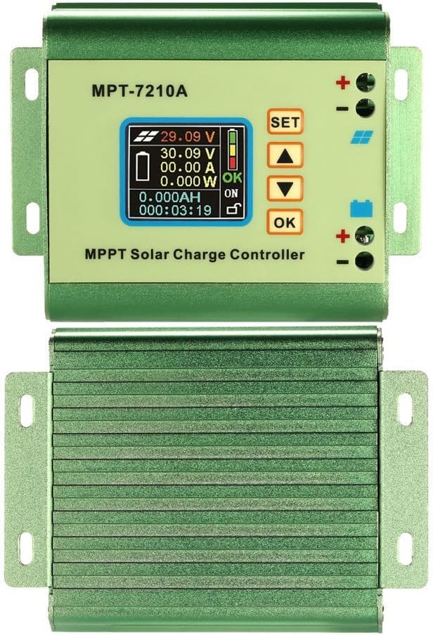
Figure 2: Top and bottom view of the controller, illustrating the battery and PV input terminals.

Figure 3: Physical dimensions of the MPT-7210A controller, including mounting hole distances.
5. Operating Instructions
The MPT-7210A features a color LCD display and interactive buttons for easy operation.
5.1. Control Buttons

Figure 4: Diagram showing the function of each control button on the MPT-7210A.
- SET: Used to enter data setting mode or confirm selections.
- UP (▲): Increases values, adjusts brightness (long press).
- DOWN (▼): Decreases values, calibrates current to zero (long press).
- OK: Validates data, turns ON/OFF output, locks/unlocks buttons (long press).
5.2. Setting Parameters
To set parameters like output voltage or current:
- Press the SET button to enter the data group setting interface.
- Use the UP (▲) or DOWN (▼) buttons to select a parameter or a previously stored data set.
- Press SET again to confirm selection and enter value adjustment mode.
- Use UP (▲) or DOWN (▼) to adjust the value.
- Press OK to validate the new setting.

Figure 5: Example of the LCD screen during parameter setting.
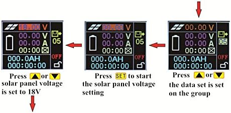
Figure 6: Further illustration of the parameter setting process on the LCD.
6. Display Interface
The color LCD provides comprehensive real-time information about your solar charging system:

Figure 7: Detailed breakdown of the MPT-7210A LCD display elements.
- Current Solar Panel Voltage: Displays the real-time voltage from your PV array.
- Battery Charging Voltage: Shows the voltage currently being supplied to the battery.
- Battery Charging Current: Indicates the current flowing into the battery.
- Charging Power: Displays the instantaneous power being delivered to the battery.
- Cumulative Charge Capacity: Tracks the total Amp-hours charged.
- Cumulative Charging Time: Shows the total duration of charging.
- Charging Stage Directions: Visual indicators for the current charging phase (e.g., Bulk, Absorption, Float).
- Charge Status Indication: Provides a quick overview of the charging state.
- Open Output Status Indication: Shows if the load output is active.
- Key Lock Status: Indicates if the control buttons are locked to prevent accidental changes.
7. Maintenance
To ensure the longevity and optimal performance of your MPT-7210A Solar Charge Controller, regular maintenance is recommended:
- Inspect Connections: Periodically check all wiring connections for tightness and ensure there are no signs of corrosion or damage.
- Clean Controller: Keep the controller's exterior clean and free from dust, dirt, and debris. A clean surface ensures proper heat dissipation.
- Check Solar Panels: Ensure your solar panels are clean and free from obstructions (e.g., leaves, snow) to maximize sunlight absorption.
- Monitor Performance: Regularly observe the display for any unusual readings or error messages.
8. Troubleshooting
If you encounter issues with your MPT-7210A, consider the following:
- No Display/Power: Verify that all battery and solar panel connections are secure and correctly polarized. Ensure the battery has sufficient charge to power the controller.
- No Charging: Check if solar panels are receiving adequate sunlight. Inspect solar panel wiring for any breaks or loose connections. Confirm the selected charging mode is appropriate for your battery type.
- Incorrect Readings: Ensure all connections are tight and free from corrosion. If issues persist, refer to the detailed display interface section for understanding specific indicators.
- Overheating: Ensure the controller has sufficient ventilation and is not installed in an enclosed space without airflow.
9. Technical Specifications
| Feature | Specification |
|---|---|
| Model | MPT-7210A |
| Brand | MPT |
| Input Voltage | DC12-60V |
| Output Voltage | DC15V-90V (Adjustable) |
| Output Current | 0-10A (Adjustable) |
| Output Power | Max 600W |
| Display Type | Color LCD |
| Operating Modes | MPPT / DC-DC |
| Data Storage | 20 sets |
| Dimensions (Approx.) | 131mm x 103.5mm x 55mm |
| Mounting Hole Distance | 117mm (long side), 43mm (short side) |
| UPC | 600682249102 |
10. Warranty and Support
For technical assistance, troubleshooting, or warranty inquiries, please contact your retailer or the manufacturer directly. Keep your purchase receipt as proof of purchase for any warranty claims.