1. Introduction
This manual provides essential information for the safe and effective installation, operation, and maintenance of the Packard C240C 2-Pole Definite Purpose Contactor. Please read this manual thoroughly before attempting any installation or operation to ensure proper function and to prevent potential hazards.
The Packard C240C is designed for use in various industrial and commercial applications, conforming to UL Bulletin No. 508 "Industrial Contactor Control Equipment" and meeting specifications for devices up to 600 VAC.
2. Safety Information
WARNING: Electrical shock hazard. Installation and servicing should only be performed by qualified personnel.
- Always disconnect power at the main circuit breaker or fuse box before installing or servicing the contactor.
- Ensure all wiring complies with national and local electrical codes.
- Verify the voltage and current ratings of the contactor match the application requirements.
- Do not operate the contactor if it appears damaged.
- Wear appropriate personal protective equipment (PPE), including insulated gloves and safety glasses.
3. Product Description and Features
The Packard C240C is a 2-pole definite purpose contactor engineered for reliability and performance in demanding electrical systems. Key features include:
- UL Compliance: Conforms to UL Bulletin No. 508 for Industrial Contactor Control Equipment, suitable for devices up to 600 VAC.
- Contact Material: Silver-plated contacts with a protective cover for enhanced durability and conductivity.
- Terminals: Equipped with box lugs and spade terminals as standard for versatile wiring options.
- Coil Insulation: Features Class B Coil insulation for reliable operation.
- Auxiliary Options: UL and cUL recognized auxiliary switch and replacement coil available (sold separately).
- Frequency: Operates on 50/60 Hz systems.
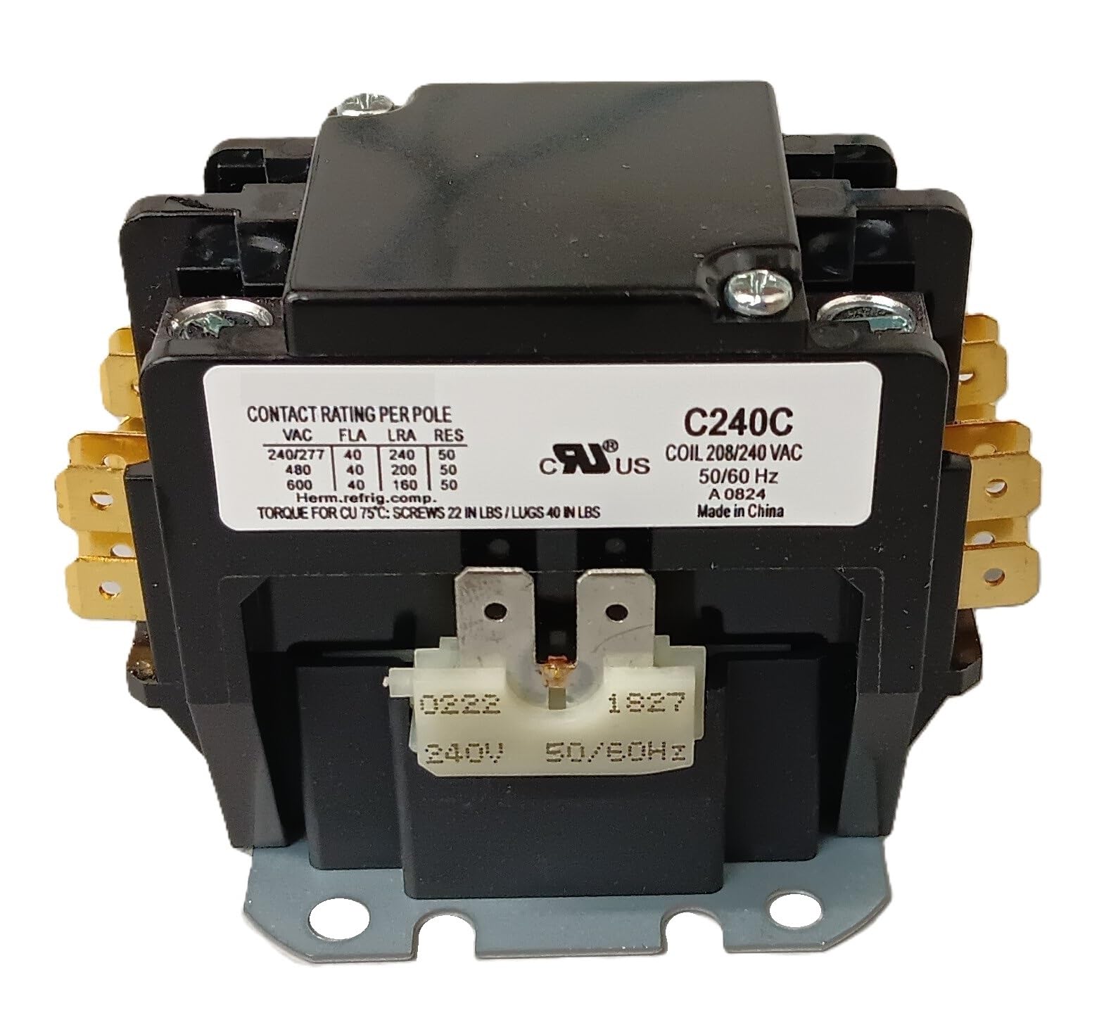
Figure 1: Front view of the Packard C240C Contactor, highlighting the main power terminals.
4. Specifications
| Parameter | Value |
|---|---|
| Model Number | C240C |
| Poles | 2 |
| F/L Inductive Amps | 40 A |
| Resistive Amps | 50 A |
| Coil Voltage | 208/240 VAC |
| Frequency | 50/60 Hz |
| Coil Insulation | Class B |
| Product Dimensions | 4.49 x 2.6 x 2.6 inches |
| Item Weight | 10.4 ounces |
| Compliance | UL Bulletin No. 508, UL and cUL recognized |
5. Setup and Installation
Proper installation is crucial for the safe and reliable operation of the contactor. It is highly recommended that installation be performed by a licensed electrician or qualified service technician.
- Power Disconnection: Ensure all power to the circuit where the contactor will be installed is completely disconnected and locked out. Verify with a voltage tester.
- Mounting: Securely mount the contactor in a suitable enclosure or panel using appropriate fasteners. The mounting plate is designed for easy installation.
- Wiring Main Power: Connect the main power lines to the load terminals (typically larger terminals) of the contactor. Ensure connections are tight and secure. The box lugs and spade terminals accommodate various wire sizes.
- Wiring Coil Control: Connect the control circuit wires to the coil terminals. The coil voltage for this model is 208/240 VAC. Incorrect coil voltage can damage the contactor.
- Verification: Double-check all wiring connections for tightness and correct polarity. Ensure no bare wires are exposed.
- Enclosure: Close and secure the electrical enclosure.
- Power Restoration: Restore power to the circuit.

Figure 2: Side view illustrating the mounting plate of the contactor.

Figure 3: Detail of the main power terminals for wiring connections.

Figure 4: Rear view showing the coil terminals for control wiring.
6. Operating Instructions
The Packard C240C contactor operates by energizing its coil, which creates a magnetic field to close the main power contacts, allowing current to flow to the connected load.
- When the control circuit supplies 208/240 VAC to the coil terminals, the coil energizes.
- The energized coil pulls the armature, causing the main power contacts to close.
- Current then flows through the main contacts to the connected load (e.g., motor, heating element).
- When power to the coil is removed, the magnetic field collapses, and springs return the contacts to their open (de-energized) position, interrupting power to the load.
Ensure the control circuit is properly configured to provide the correct voltage to the coil when the load needs to be activated.
7. Maintenance
Regular inspection and maintenance can extend the life of your contactor and ensure safe operation. Always disconnect power before performing any maintenance.
- Visual Inspection (Monthly): Check for any signs of overheating, such as discoloration or melted insulation. Look for loose connections, corrosion, or excessive dust accumulation.
- Contact Inspection (Annually or as needed): Inspect the main contacts for excessive pitting or wear. While silver-plated contacts are durable, heavy arcing can cause degradation over time. If contacts are severely worn, the contactor should be replaced.
- Cleaning: Use a dry, non-conductive brush or compressed air to remove dust and debris from the contactor. Do not use solvents or liquids.
- Terminal Tightness: Periodically check and tighten all terminal screws to ensure good electrical contact and prevent overheating.
8. Troubleshooting
If the contactor is not functioning as expected, refer to the following troubleshooting guide:
| Problem | Possible Cause | Solution |
|---|---|---|
| Contactor does not energize (contacts do not close) | No control voltage to coil; Incorrect coil voltage; Open coil; Loose wiring connection. | Check control circuit for power; Verify coil voltage matches supply; Test coil for continuity (replace if open); Tighten all coil wiring connections. |
| Contactor hums loudly | Loose shading coil; Dirt/debris on magnet faces; Incorrect voltage. | Inspect and secure shading coil; Clean magnet faces; Verify correct coil voltage. |
| Contactor contacts weld shut or overheat | Overload condition; Short circuit; Frequent cycling; Undersized contactor; Loose power connections. | Check load for overcurrent; Inspect circuit for shorts; Reduce cycling frequency if possible; Ensure contactor is rated for the application; Tighten all power wiring connections. Replace contactor if contacts are welded. |
| Contactor fails to de-energize | Contacts welded; Control circuit continuously energized. | Replace contactor; Check control circuit for faults or stuck relays/switches. |
If troubleshooting steps do not resolve the issue, contact a qualified technician or Packard customer support.
9. Warranty and Support
For specific warranty information regarding your Packard C240C Definite Purpose Contactor, please refer to the documentation provided at the time of purchase or visit the official Packard website. General support and technical assistance can be obtained by contacting Packard customer service.
Packard Customer Support:
- Website: www.packardonline.com (Note: This is a placeholder URL, please verify the actual support website.)
- Contact information may also be found on the product packaging or included inserts.


