1. Introduction
Thank you for choosing the KOLINK Refractor Midi-Tower computer case. This manual provides essential information for the proper installation, operation, and maintenance of your new PC chassis. Please read this manual carefully before beginning the assembly process to ensure a smooth and safe build.
1.1 Safety Information
- Always disconnect the power supply from the wall outlet before installing or removing any components.
- Wear an anti-static wrist strap to prevent electrostatic discharge (ESD) damage to sensitive components.
- Handle components with care. Avoid touching pins or circuit boards directly.
- Keep small parts and tools away from children.
- Ensure proper ventilation around the case to prevent overheating.
2. Package Contents
Please verify that all the following items are present in your package:
- KOLINK Refractor Midi-Tower Chassis
- Accessory Box (containing screws, standoffs, cable ties, etc.)
- User Manual (this document)
If any items are missing or damaged, please contact your retailer or KOLINK support.
3. Product Overview
Familiarize yourself with the key features and components of your KOLINK Refractor Midi-Tower.
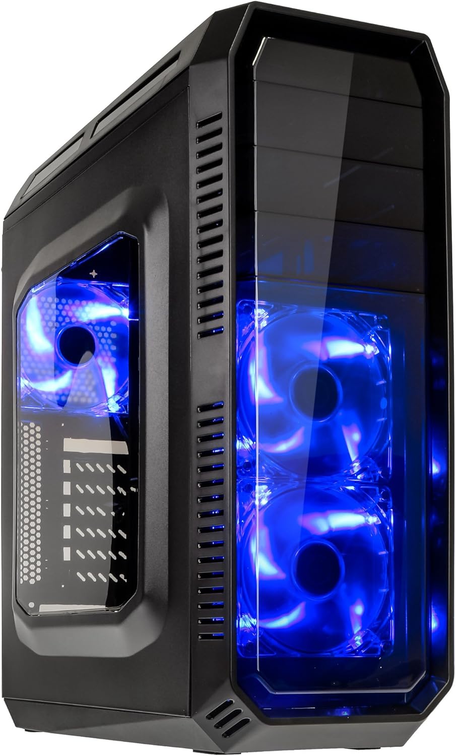
This image displays the KOLINK Refractor Midi-Tower from a front-left perspective, highlighting its sleek black design. The front panel features two pre-installed 120mm blue LED fans, visible through a transparent section, providing both cooling and aesthetic appeal. The left side panel includes a window, allowing visibility of internal components.

A top-front view of the case, illustrating the conveniently located I/O panel on the top. This panel includes two USB 3.0 ports, two USB 2.0 ports, and audio input/output jacks. The top surface also features a mesh area for additional ventilation, contributing to optimal airflow.

This image shows the right side panel of the KOLINK Refractor Midi-Tower. It is a solid black panel, designed for cable management behind the motherboard tray, ensuring a clean and organized interior.

This composite image provides three distinct views of the case. The left panel shows the front with its blue LED fans. The middle panel displays the rear of the case, featuring the motherboard I/O cutout, seven expansion slots, and a 120mm fan mount. The right panel offers a close-up of the top I/O ports, including USB 3.0, USB 2.0, and audio jacks.

A detailed close-up of the top I/O panel. It clearly shows the power and reset buttons, two USB 3.0 ports, two USB 2.0 ports, and the microphone and headphone jacks, providing easy access for peripherals.
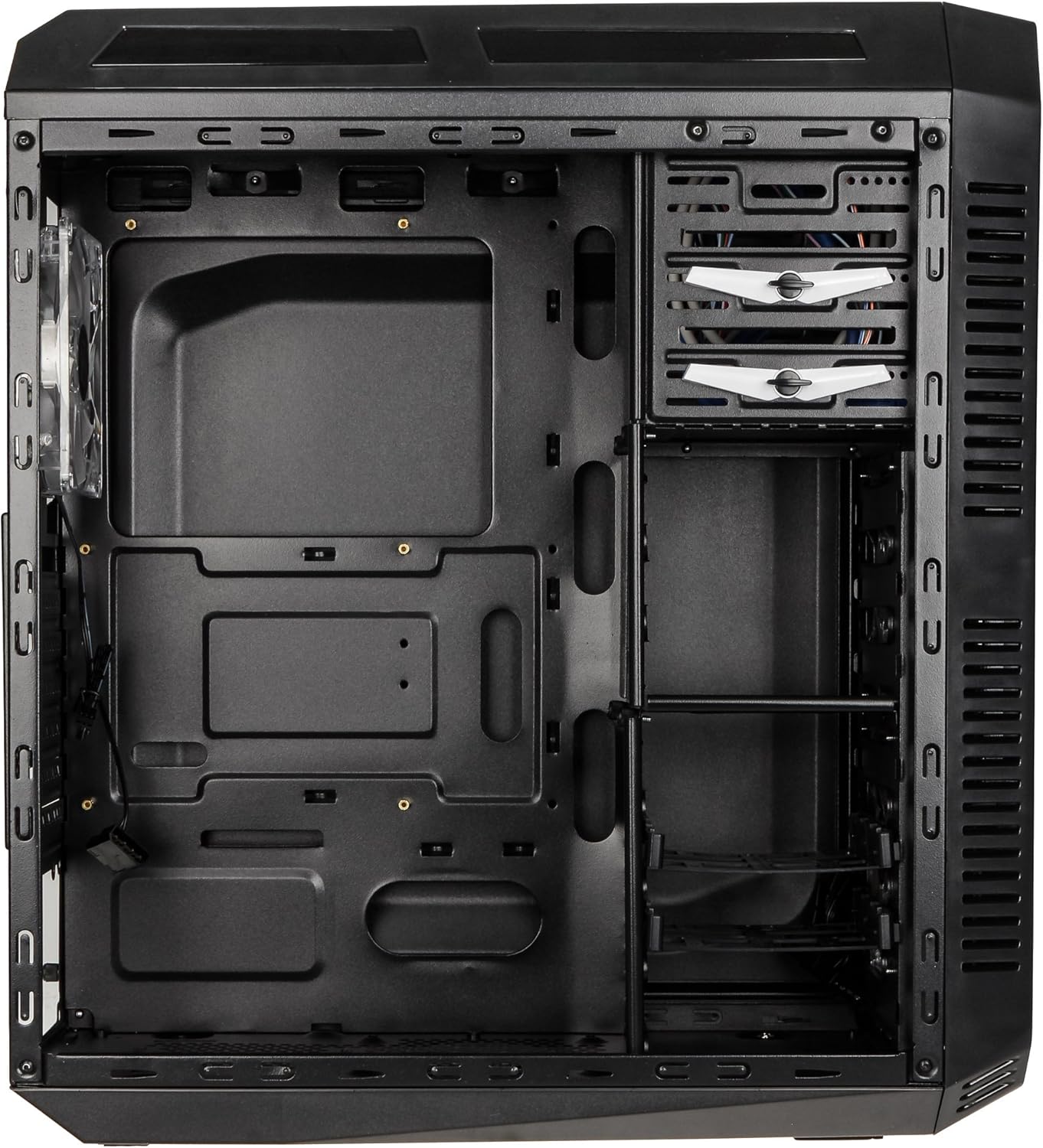
This image presents the interior of the case from the left side, revealing the spacious motherboard tray compatible with ATX motherboards. It features a large cutout behind the CPU area for easy cooler installation and multiple grommeted holes for efficient cable routing.

An internal view from the right side, focusing on the drive bay configuration. The case offers three external 5.25-inch bays and seven internal 2.5/3.5-inch drive bays, providing ample storage expansion options.

A closer look at the internal drive bays, illustrating the design for mounting 2.5-inch or 3.5-inch storage drives. These bays are designed for easy installation and removal of hard drives and SSDs.

This image provides an internal view looking down from the top, showcasing the pre-installed 120mm blue LED fan at the rear for exhaust. The top panel's mesh area for additional fan mounting is also visible, contributing to overall system cooling.
4. Setup and Installation
Follow these steps to install your computer components into the KOLINK Refractor Midi-Tower.
4.1 Preparing the Case
- Place the case on a flat, stable surface.
- Remove the left and right side panels by unscrewing the thumbscrews at the rear of the case and sliding the panels backward.
4.2 Motherboard Installation
- Install the I/O shield that came with your motherboard into the cutout at the rear of the case.
- Ensure the correct motherboard standoffs are installed for your ATX motherboard. Adjust or add standoffs as necessary using the provided accessory kit.
- Carefully place your motherboard onto the standoffs, aligning the screw holes.
- Secure the motherboard with the appropriate screws from the accessory kit.
4.3 Power Supply Installation
- Position your ATX power supply unit (PSU) in the designated compartment at the bottom rear of the case.
- Align the PSU with the screw holes at the rear of the case.
- Secure the PSU using the screws provided with your power supply.
4.4 Drive Installation
5.25-inch External Drives:
- Remove the desired 5.25-inch bay cover from the front panel.
- Slide your optical drive or other 5.25-inch device into the bay from the front.
- Secure the drive using the tool-less clips or screws.
2.5/3.5-inch Internal Drives:
- Locate the internal drive bays.
- Mount your 2.5-inch SSD or 3.5-inch HDD into the drive trays.
- Slide the populated drive trays back into the drive cage until they click into place.
4.5 Expansion Card Installation
- Remove the necessary expansion slot covers at the rear of the case.
- Insert your graphics card or other PCIe expansion card into the corresponding slot on the motherboard.
- Secure the card with the provided screws.
4.6 Cable Management
Utilize the cable routing holes and tie-down points behind the motherboard tray to organize cables. This improves airflow and gives your build a cleaner appearance.
4.7 Fan Installation (Optional)
The case comes with two 120mm blue LED fans pre-installed at the front and one 120mm blue LED fan at the rear. Additional fan mounting locations include:
- Top: 1x 120/140mm fan
- Bottom: 1x 120mm fan (under the PSU)
Install additional fans as needed for optimal cooling, ensuring proper airflow direction.
5. Operating Instructions
5.1 Initial Power On
- Once all components are installed and cables are connected, replace both side panels.
- Connect your monitor, keyboard, mouse, and other peripherals.
- Connect the power cable to the PSU and then to a wall outlet.
- Press the power button on the top I/O panel to start your system.
5.2 Front Panel I/O Usage
The top I/O panel provides convenient access to:
- USB 3.0 Ports (x2): For high-speed data transfer with compatible devices.
- USB 2.0 Ports (x2): For connecting standard USB devices.
- Audio Jacks (Headphone/Microphone): For connecting headsets or external audio devices.
- Power Button: To turn the system on/off.
- Reset Button: To restart the system.
5.3 LED Lighting
The pre-installed front and rear fans feature blue LED lighting, which illuminates when the system is powered on, adding an aesthetic element to your build.
6. Maintenance
Regular maintenance helps ensure optimal performance and longevity of your computer system.
6.1 Cleaning
- Dust Filters: The case includes a removable dust filter under the PSU. Regularly remove and clean this filter to prevent dust buildup and maintain airflow.
- Exterior: Wipe the exterior surfaces with a soft, damp cloth. Avoid abrasive cleaners.
- Interior: Periodically use compressed air to remove dust from internal components and fan blades. Ensure the system is powered off and unplugged before cleaning the interior.
6.2 Airflow Optimization
Ensure that the case's ventilation areas (front, top, rear, bottom) are not obstructed. Proper cable management also contributes significantly to unrestricted airflow within the case.
7. Troubleshooting
This section addresses common issues you might encounter.
7.1 Common Issues
- System Not Powering On:
- Check if the power cable is securely connected to both the PSU and the wall outlet.
- Ensure the PSU switch is in the 'ON' position.
- Verify that the front panel power button cable is correctly connected to the motherboard.
- Confirm all internal power cables (24-pin ATX, CPU, GPU) are properly seated.
- Fans Not Spinning:
- Check if the fan power cables are correctly connected to the motherboard or fan controller.
- Ensure the system is receiving power.
- USB Ports Not Working:
- Verify that the front panel USB 3.0 and USB 2.0 headers are correctly connected to the motherboard.
- Ensure the device you are connecting is functioning correctly.
- Audio Ports Not Working:
- Check that the front panel audio header (HD Audio) is correctly connected to the motherboard.
- Confirm your audio drivers are installed and up to date.
For further assistance, please refer to your motherboard manual or contact KOLINK support.
8. Specifications
Detailed technical specifications for the KOLINK Refractor Midi-Tower.
| Feature | Specification |
|---|---|
| Model Name | Refractor Midi-Tower |
| Dimensions (W x H x D) | 190 x 475 x 445 mm (7.5 x 18.7 x 17.5 inches) |
| Material | Steel (body), Plastic (front) |
| Weight | Approx. 4.8 kg (10.6 lbs) |
| Colour | Black |
| Form Factor | Midi Tower |
| Motherboard Compatibility | ATX |
| External Drive Bays | 3x 5.25-inch |
| Internal Drive Bays | 7x 2.5/3.5-inch |
| Expansion Slots | 7 |
| Pre-installed Fans | 2x 120mm (front, blue LED), 1x 120mm (rear, blue LED) |
| Fan Support (Total Possible) | Front: 2x 120mm, Top: 1x 120/140mm, Bottom: 1x 120mm, Rear: 1x 120mm |
| I/O Panel | 2x USB 3.0, 2x USB 2.0, 1x Audio In/Out |
| Maximum Graphics Card Length | 360 mm |
| Maximum CPU Cooler Height | 174 mm |
| PSU Compatibility | Standard ATX (optional) |
| Dust Filters | Floor (under PSU, removable) |
9. Warranty and Support
KOLINK products are manufactured to high-quality standards. This product is covered by a manufacturer's warranty against defects in materials and workmanship. The specific terms and duration of the warranty may vary by region and retailer.
Please retain your proof of purchase for warranty claims. For technical support, warranty inquiries, or to report missing/damaged parts, please contact your point of purchase or visit the official KOLINK website for support resources.
KOLINK Official Website: www.kolink.eu (Please note: This is a general link and may not lead directly to a support page for this specific model.)


