1. Introduction
The INIM ELECTRONICS BD-D060 Optical Barrier is a sophisticated security device designed for perimeter protection. It utilizes double radii optical technology to detect intrusions over a 60-meter range. This manual provides essential information for the proper installation, operation, and maintenance of your BD-D060 optical barrier.
Please read this manual thoroughly before attempting to install or operate the device. Retain this manual for future reference.
2. Safety Information
- Installation and servicing must be performed by qualified personnel only.
- Disconnect power before performing any installation or maintenance procedures.
- Ensure all wiring complies with local electrical codes and regulations.
- Do not expose the device to extreme temperatures or direct water spray beyond its IP54 rating.
- This device is designed for security detection and should not be used for life safety applications unless explicitly certified for such use.
3. Package Contents
Verify that all components are present and undamaged upon unpacking:
- BD-D060 Optical Barrier Transmitter Unit
- BD-D060 Optical Barrier Receiver Unit
- Mounting Brackets and Hardware
- Alignment Tools (if included)
- User Manual (this document)
4. Product Overview
The BD-D060 Optical Barrier consists of a transmitter and a receiver unit that create an invisible infrared beam. When this beam is interrupted, an alarm signal is generated.
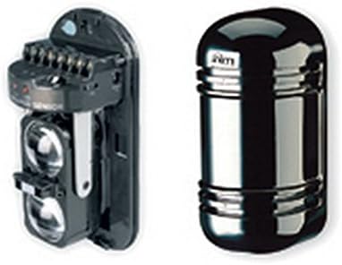
Figure 1: BD-D060 Optical Barrier Components. The image displays two main components of the BD-D060 Optical Barrier. On the left is the internal assembly of the barrier, showing the optical lenses and terminal connections. On the right is the external casing, a sleek, dark, cylindrical unit designed to protect the internal components.
Key features include:
- 60m double radii optical barrier for enhanced detection.
- Horizontal and vertical spoke adjustment for precise alignment.
- IP54 rated enclosure for protection against dust and splashing water.
- Programmable intervention time to customize alarm response.
5. Setup and Installation
Proper installation is crucial for optimal performance. Follow these general steps:
- Site Selection: Choose a location free from obstructions that could block the beam. Ensure stable mounting surfaces.
- Mounting: Securely mount the transmitter and receiver units facing each other, ensuring they are at the same height and within the 60m range. Use the provided mounting brackets.
- Wiring: Connect power and alarm output wires to the respective terminals on both units. Refer to the wiring diagram provided with the product for specific connections.
- Alignment: Power on the units. Use the horizontal and vertical adjustment mechanisms to precisely align the transmitter and receiver beams. Most units include visual indicators (e.g., LEDs) or audible tones to assist with alignment.
- Configuration: Set the desired intervention time and other parameters using the internal jumpers or dip switches as per the detailed product sheet.
6. Operating the Device
Once installed and aligned, the BD-D060 operates automatically. The system is active when powered on and properly aligned.
- Normal Operation: When the beam is clear, the alarm output remains in its normal state (e.g., closed contact).
- Alarm Condition: If the infrared beam is interrupted for the programmed intervention time, the alarm output will change state (e.g., open contact), signaling an intrusion to the connected alarm panel.
- Status Indicators: Observe the status LEDs on the units for operational status (e.g., power, alignment, alarm). Consult the detailed product sheet for LED indicator meanings.
7. Maintenance
Regular maintenance ensures the longevity and reliability of your optical barrier.
- Cleaning: Periodically clean the optical lenses of both the transmitter and receiver units using a soft, lint-free cloth. Dust, dirt, or spiderwebs can obstruct the beam and cause false alarms.
- Alignment Check: Verify the alignment of the units periodically, especially after strong winds or physical disturbances. Re-align if necessary.
- Power Supply Check: Ensure the power supply is stable and within the specified voltage range.
- Environmental Inspection: Check for any new obstructions (e.g., growing vegetation) that might interfere with the beam path.
8. Troubleshooting
If you experience issues with your BD-D060, refer to the following common problems and solutions:
| Problem | Possible Cause | Solution |
|---|---|---|
| False Alarms | Misalignment, dirty lenses, beam obstruction (e.g., vegetation, insects), strong sunlight interference. | Re-align units, clean lenses, remove obstructions, check for proper shielding from direct sunlight. |
| No Alarm on Intrusion | Units not powered, severe misalignment, faulty wiring, damaged unit. | Check power supply, re-align units, inspect wiring connections, test units individually. |
| Status LED Off | No power, faulty unit. | Verify power connection and supply, contact technical support if power is present. |
For persistent issues, contact INIM ELECTRONICS technical support.
9. Specifications
| Feature | Detail |
|---|---|
| Model | BD-D060 |
| Manufacturer | Inim |
| Detection Range | 60 meters (double radii) |
| Adjustment | Horizontal and vertical spoke adjustment |
| Ingress Protection (IP) Rating | IP54 |
| Intervention Time | Programmable |
| Batteries Included | No |
| Batteries Required | No |
| ASIN | B01CNOY16Y |
| Date First Available | 6 Mar. 2016 |
10. Warranty and Support
This product is covered by a standard manufacturer's warranty. For specific warranty terms and conditions, please refer to the documentation provided with your purchase or visit the official INIM ELECTRONICS website.
For technical support, service, or replacement parts, please contact your authorized INIM ELECTRONICS dealer or distributor. Ensure you have your product model number (BD-D060) and purchase details available when seeking support.


