1. Introduction
This manual provides comprehensive instructions for the safe and effective installation, operation, and maintenance of the Cisa 601/T Door Closer. Designed for reliable door control, this unit ensures doors close smoothly and securely. Please read these instructions carefully before beginning installation or operation to ensure proper function and longevity of the product.
2. Safety Information
Always observe the following safety precautions:
- Ensure all components are present and undamaged before installation.
- Wear appropriate personal protective equipment (PPE), such as safety glasses and gloves, during installation.
- Do not attempt to modify the door closer. Unauthorized modifications can compromise safety and void the warranty.
- Keep children and pets away from the installation area.
- Ensure the door closer is securely fastened to prevent accidental detachment.
- Adjustments to closing speed and latching force should be made carefully to avoid injury or damage to the door/frame.
3. Package Contents
Verify that all the following items are included in your package:
- Cisa 601/T Door Closer Unit
- Mounting Arm Assembly
- Mounting Screws and Fasteners
- Installation Template (if applicable)
- Instruction Manual (this document)
4. Setup (Installation)
The Cisa 601/T Door Closer is designed for screw-on installation. Follow these general steps for proper mounting:
- Prepare the Door and Frame: Determine the desired mounting position (e.g., standard arm, parallel arm, top jamb) based on door type and opening direction. Ensure the mounting surface is clean, flat, and structurally sound.
- Mark Drilling Points: Use the provided template (if available) or measure carefully to mark the drilling points for the door closer body and the arm bracket.
- Drill Pilot Holes: Drill pilot holes at the marked positions, ensuring they are of the correct size for the mounting screws.
- Mount the Closer Body: Securely attach the door closer body to the door or frame using the provided screws. Ensure it is level and firmly fixed.
- Install the Arm Assembly: Attach the main arm to the closer spindle. Then, attach the shoe bracket to the door frame or door, depending on the mounting type. Connect the arm to the shoe bracket.
- Adjust Arm Length: Adjust the length of the arm to achieve the correct angle for optimal closing action.
- Initial Adjustments: Perform initial adjustments for closing speed and latching force as described in the 'Operating Instructions' section.
Product Image:
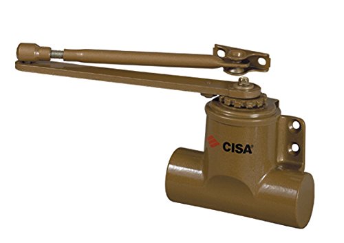
This image displays the Cisa 601/T door closer unit. It features a gold-colored cast iron body, indicating its robust construction and aesthetic finish. The design suggests it is a hydraulic door closer, typically mounted on the door frame or door leaf to control the closing speed and force of a door.
5. Operating Instructions
The Cisa 601/T Door Closer is designed to automatically close a door after it has been opened. Its primary function is to control the closing speed and the final latching action of the door. Adjustments are typically made via two or more adjustment valves located on the closer body.
- Closing Speed Adjustment: This valve controls the speed at which the door closes from its fully open position until approximately 10-15 degrees from the frame. Turn the valve clockwise to decrease speed (slower closing) and counter-clockwise to increase speed (faster closing). Make small adjustments and test the door's closing action.
- Latching Speed/Force Adjustment: This valve controls the speed and force of the door's final closing action, typically the last 10-15 degrees, to ensure the latch engages properly. Turn the valve clockwise to decrease latching speed/force and counter-clockwise to increase it. This adjustment is crucial for ensuring the door closes completely without slamming.
Important: Do not overtighten adjustment valves. Excessive force can damage the internal mechanism. Always test the door's closing action after each adjustment.
6. Maintenance
Regular maintenance ensures the optimal performance and longevity of your Cisa 601/T Door Closer.
- Periodic Inspection: Annually inspect the door closer, mounting screws, and arm assembly for any signs of looseness, wear, or damage. Tighten any loose screws.
- Cleaning: Wipe the door closer body with a soft, damp cloth to remove dust and grime. Avoid using abrasive cleaners or solvents.
- Lubrication: The internal hydraulic mechanism is factory-sealed and does not require lubrication. Do not attempt to open the closer body.
- Functionality Check: Periodically check the closing and latching speeds to ensure they are still set correctly. Readjust if necessary.
7. Troubleshooting
If you encounter issues with your Cisa 601/T Door Closer, refer to the following common problems and solutions:
| Problem | Possible Cause | Solution |
|---|---|---|
| Door closes too fast/slow | Incorrect closing speed adjustment | Adjust the closing speed valve (refer to Section 5). |
| Door does not latch | Insufficient latching force/speed | Adjust the latching speed/force valve (refer to Section 5). Ensure door alignment is correct. |
| Door slams shut | Latching speed too high or closing speed too high | Decrease latching speed and/or closing speed (refer to Section 5). |
| Oil leakage | Damaged seals or closer body | Discontinue use immediately. Contact Cisa customer support for replacement. Do not attempt to repair. |
| Closer arm loose | Loose mounting screws | Tighten all mounting screws. Inspect for stripped threads or damaged components. |
8. Specifications
| Feature | Detail |
|---|---|
| Brand | Cisa |
| Model Number | 60150 (Reference: 26850) |
| Type | Door Closer 601/T |
| Material | Cast Iron (Fer) |
| Finish | Gold (Or) |
| Force | N° 3 |
| Item Weight | 8 kilograms (17.64 pounds) |
| Installation Method | Screw-on (À visser) |
| Quantity per package | 1 |
9. Warranty and Support
Specific warranty information for the Cisa 601/T Door Closer is not provided in the product data. For details regarding warranty coverage, terms, and conditions, please refer to the documentation included with your purchase or contact Cisa customer support directly.
For technical assistance, spare parts, or further inquiries, please contact the manufacturer or your authorized dealer. When contacting support, please have your product model number (60150 or 26850) and purchase date available.


