Introduction
This manual is a digitally enhanced reproduction of the original manufacturer-issued service manual for John Deere 300, 312, 314, and 316 Lawn & Garden Tractors. It provides comprehensive instructions for taking the tractor apart, performing repairs, and reassembling it. This resource is essential for serious repairs or restoration projects, offering detailed information such as specifications, torque values, and operational ranges.
All information, illustrations, and specifications contained in this service manual are based on the latest information available at the time of publication. John Deere reserves the right to make changes at any time without prior notice.
Section 10: General
Group 5: Tractor Identification
This section details how to identify your tractor using serial numbers.
- Serial Numbers
- Tractor Serial Number
- Engine Serial Number
- Transmission Serial Number
Group 10: Specifications
Refer to this group for detailed specifications of the 300 and 316 tractor models.
- 300 and 316 Tractor Specifications
- 312 Tractor Specifications
- Torque Charts
- Bolt Torque Chart
- Set Screw Seating Torque Chart
Group 15: Fuel and Lubricants
This group provides information on fuel types, lubricants, capacities, and service intervals.
- Fuel
- Lubricants (Engine Oil, Hydraulic Oil, Grease)
- Capacities
- Service Intervals
- Checking Transmission Fluid Level
- Changing Transmission Fluid and Filter
- Checking Engine Crankcase Oil Level
- Changing Engine Crankcase Oil
- Lubricating Grease Fittings

Figure: Lubricating Grease Fittings. This image displays diagrams for lubricating grease fittings on various parts of the John Deere 300, 312, 314, and 316 tractors. It includes illustrations for lubricating the steering column on 300 tractors, front wheels, axle spindles, and brake pedal shaft on 314 tractors, hydraulic lift lever shaft on 300 tractors, and a general diagram for lubricating the steering column on 314 tractors. Specific serial number ranges are noted for each diagram.
Lubricate fittings as illustrated in the diagrams using a John Deere Pisto-Luber or hand grease gun. Clean fittings before and after lubrication. Address excessive play or difficult movement of the steering pivot by removing Teflon washers and adjusting or lubricating as needed.
Group 20: Tune-up and Adjustments
This group covers procedures for engine tune-up and various tractor adjustments.
- Purpose of Instructions
- Engine Tune-up: Clean Air Intake Screens and Cooling Fins, Test Compression, Check Spark Plug Gap, Test Crankcase Vacuum, Check Breaker Points, Adjust Breaker Points, Time Engine, Clean Air Cleaner Element, Adjust Carburetor, Adjust Anti-Dieseling Solenoid, Change Engine Oil, Service Battery, Install Grille, Hood and Side Panels.
- Tractor Adjustment Guide: Check Transmission Fluid Level, Change Transmission Fluid and Filter, Lubricate Grease Fittings, Adjust Brakes, Adjust Hydrostatic Linkage, Check Hydraulic System, Charge Pressure, Adjust Steering Gear, Adjust Steering Backlash, Adjust Front Wheel Toe-in, Clean Fuel Strainer, Check Wiring, Check Belts and Equipment, Check Tire Pressure.
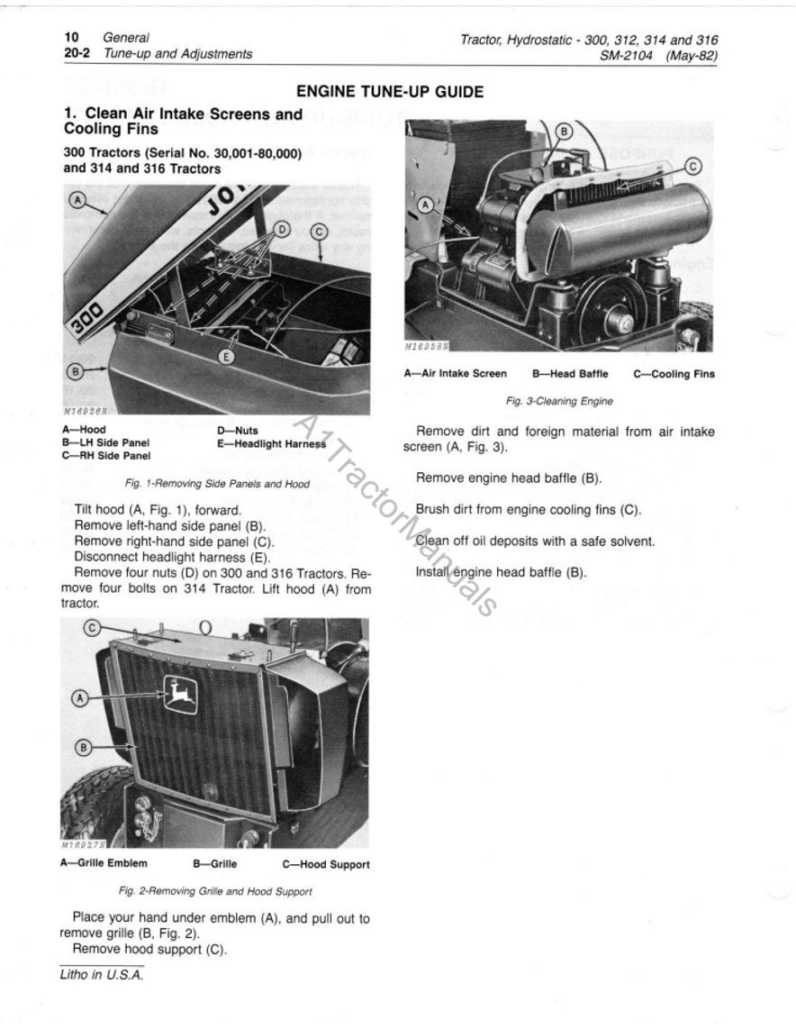
Figure: Engine Tune-up Guide - Clean Air Intake Screens and Cooling Fins. This image illustrates the process of cleaning air intake screens and cooling fins on John Deere 300, 314, and 316 Tractors (Serial No. 30,001-80,000). Figure 1 shows removing side panels and the hood, identifying components like the air intake screen, LH side panel, hood, nuts, and headlight harness. Figure 2 shows removing the grille and hood support, identifying the grille emblem, grille, and hood support. Figure 3 details cleaning the engine, specifically the air intake screen, head baffle, and cooling fins, and provides instructions for removing dirt and foreign material.

Figure: Adjust Brakes and Hydrostatic Linkage. This image provides diagrams and instructions for adjusting the brakes and hydrostatic linkage on John Deere tractors. Figure 30 illustrates adjusting brakes, showing the pin, yoke, and link components. Figure 31 shows the brake lock and second notch for parking brake adjustment. Figure 32 details adjusting hydrostatic linkage, identifying components like the cotter pin, drilled pin, clevis, control cam, roller, detent, nut, and eccentric. Instructions are provided for both brake and hydrostatic linkage adjustments, including steps for loosening, turning, and securing components.
Section 20: KOHLER K301AS, K321AQS AND K341AQS ENGINES
This section provides detailed service information for Kohler K301AS, K321AQS, and K341AQS engines used in John Deere tractors.
Group 5: General Information
Covers general information and troubleshooting for the Kohler engines.
- Diagnosing Malfunctions
- Engine Operating Balancing System
- Automatic Compression Release Camshaft
- Engine Removal: Hood, Side Panels and Grille, Hood Support, Hood and Grille on 312 Tractor.
- Disconnecting Throttle Cable, Choke Cable, Fuel Line.
- Disconnecting Wiring.
- Disconnecting Drive Shaft.
- Removing Drive Shaft on 300 Tractors (Serial No. 30,001-70,000) and all 312, 314 and 316 Tractors.
- Engine Disassembly.
Group 15: Internal Components
Detailed information on internal engine components and their service procedures.
- Inspection and Repair: Piston, Piston Ring Wear, Piston Analysis, Crankshaft, Connecting Rod and Cap, Crankshaft and Connecting Rod Wear, Camshaft, Inspecting and Repairing Balance Gears on 300 Tractor (Serial No. 30,001-73,244), Governor Components, Flywheel Ring Gear, Main Bearings, Bearing Analysis, Inspecting and Repairing Block, Deglazing Cylinder Bore, Cylinder Block Assembly.
- Installing PTO and Main Bearing.
- Installing Tappets and Camshaft.
- Installing Balance Gears and Crankshaft Without Timing Tool on 300 Tractors (Serial No. 30,001-73,244).
- Installing Balance Gears and Crankshaft With Timing Tool on 300 Tractors (Serial No. 30,001-73,244).
- Installing Flywheel and Main Bearing.
- Installing Bearing Plate.
- Adjusting Crankshaft End Play.
- Installing Oil Seals.
- Checking Piston Ring End Gap.
- Installing Piston Rings and Connecting Rod.
- Installing Ring Compressor.
- Installing Piston.
- Installing Connecting Rod Cap.
- Installing Oil Pan.
- Installing Flywheel.
- Installing Cylinder Head.
- Installing Blower Housing.
- Installing Side Air Baffle and Starter.
- Installing Air Duct and Baffles on 300, 314 and 316 Tractors.
- Installing Cooling Fin Shroud on 312 Tractor.
- Installing Breather.
- Installing Fuel Pump.
- Installing Carburetor.
- Engine Installation: Engine, Connecting Wiring, Fuel Line, Throttle Cable and Choke Cable.
- Installing Air Cleaner.
- Installing Hood, Side Panels and Grille on 300, 314 and 316 Tractors.
- Installing Hood Support, Hood and Grille on 312 Tractor.
- Removing Oil Seals.
Group 20: Specifications
Provides detailed specifications for the 300, 314, and 316 tractor engines.
- 300 and 316 Tractor Engine General Specifications: Tune-up Specifications, Internal Specifications, Torque Specifications.
- 312 Tractor Engine General Specifications: Tune-up Specifications, Internal Specifications, Torque Specifications.
- 314 Tractor Engine General Specifications: Tune-up Specifications, Internal Specifications, Torque Specifications.
Group 10: Cylinder Head, Valves and Breather - Removal
Instructions for removing components related to the cylinder head, valves, and breather.
- Removing Hood.
- Removing Side Panels.
- Removing Grille.
- Removing Hood Support.
- Removing Grille (312 Tractor).
Disassembly
- Removing Air Cleaner
- Removing Carburetor
- Removing Breather
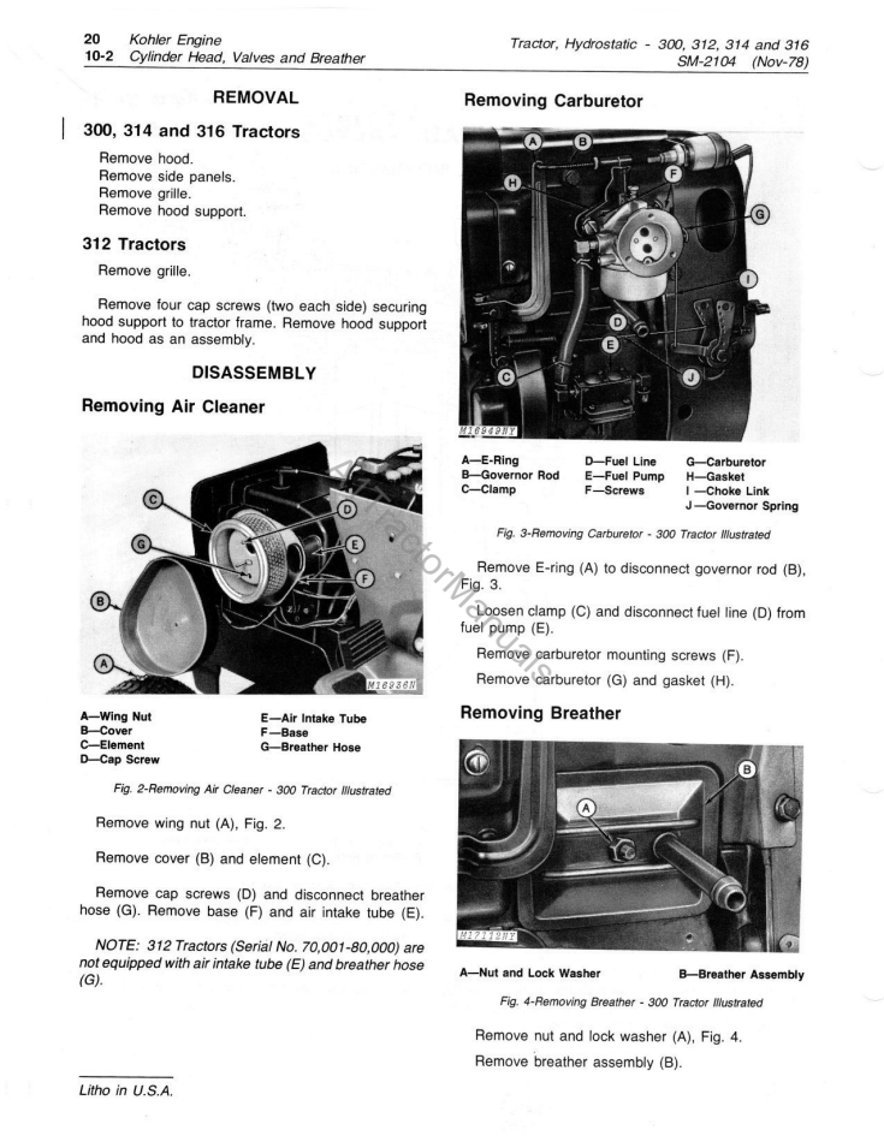
Figure: Removing Carburetor, Air Cleaner, and Breather. This image provides detailed diagrams and instructions for removing the carburetor, air cleaner, and breather from a John Deere 300 tractor. Figure 3 illustrates the carburetor components (E-ring, fuel line, carburetor, clamp, screws, governor rod, choke link, governor spring) and steps for removal. Figure 2 shows the air cleaner components (wing nut, element, cap screw, air intake tube, base, breather hose) and steps for removal. Figure 4 illustrates the breather components (nut and lock washer, breather assembly) and steps for removal. Note: 312 Tractors (Serial No. 70,001-80,000) are not equipped with air intake tube (E) and breather hose (G).
Section 30: Fuel System
This section covers the fuel system components and their maintenance.
- Group 5: General Information
- Group 10: Carburetor
- Group 15: Air Cleaner
- Group 20: Fuel Tank
- Group 25: Fuel Pump
Section 40: Electrical System
Details on the electrical components and their service.
- Group 5: General Information
- Group 10: Cranking System
- Group 15: Ignition System
- Group 20: Charging System
- Group 25: Lights and Hourmeter
- Group 30: PTO Clutch
Section 50: Power Train
Information regarding the tractor's power train system.
- Group 5: General Information
- Group 10: Drive Shaft, Couplings and Brakes
- Group 15: Hydrostatic Transmission
- Group 20: Hydrostatic Control Linkage
- Group 25: Differential and Axle
Section 60: Hydraulic System
Details on the hydraulic system components and operation.
- Group 5: General Information
- Group 10: Hydraulic Circuit
- Group 15: Hydraulic Control Valve
- Group 20: Hydraulic Cylinder
Section 70: Miscellaneous
Covers various other components not categorized elsewhere.
- Group 5: Steering Linkage
- Group 10: Front Wheels and Axles
Section 80: Special Service Tools
Lists specialized tools required for servicing these tractors.
- Group 5: Engine Convenience Service Tools
- Group 10: Tractor Convenience Service Tools
Section 90: Tractor Attachments
Information on various attachments compatible with the tractors.
- Group 5: Snow Thrower
- Group 10: 41 and 48 Rotary Mowers
- Group 15: 33 Rotary Tiller
- Group 20: 542 PTO Attachment
Warranty and Support
Information regarding product warranty and support is not provided within this service manual. For warranty details or customer support, please refer to your original purchase documentation or contact an authorized John Deere dealer.


