1. Introduction
This manual provides essential information for the proper installation, operation, and maintenance of the Honeywell R7861A1026 Burner Control Dynamic Self-Check Amplifier. This device is designed for use with 7800 Series and R7140 Relay Modules in industrial and commercial burner applications. It ensures safe and efficient burner operation by monitoring flame presence and system integrity.
The R7861A1026 amplifier features a flame failure response time of 0.8 or 3.0 seconds and provides flame signal strength readings from 0.0 to 5.0 Vdc. Its dynamic self-check capability continuously tests the flame detectors and all electronic components within the flame detection system, ensuring system reliability and safety.
2. Safety Information
WARNING:
- Installation and servicing must be performed by qualified, experienced technicians.
- Disconnect power supply before wiring connections to prevent electrical shock or equipment damage.
- Ensure all wiring complies with local and national electrical codes.
- Do not bypass or disable any safety features of the burner control system.
- Failure to follow these instructions can result in property damage, serious injury, or death.
3. Setup and Installation
The R7861A1026 amplifier is designed for plug-in installation into compatible 7800 Series relay modules. It connects via a printed circuit board edge connector, which is keyed to ensure correct orientation.
3.1 Unpacking
Carefully remove the amplifier from its packaging. Inspect for any visible damage. Do not install damaged components.
3.2 Mounting
The amplifier plugs directly into the designated slot on the 7800 Series relay module. Ensure the module is securely mounted according to its own installation instructions.
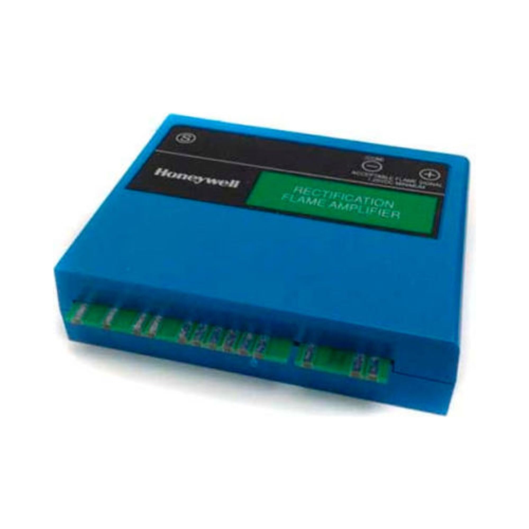
Figure 1: Honeywell R7861A1026 Burner Control Dynamic Self-Check Amplifier. This image shows the front view of the amplifier, highlighting its compact design and connection interface.
3.3 Wiring
Refer to the specific wiring diagrams provided with your 7800 Series relay module for complete system wiring. The R7861A1026 amplifier interfaces with the flame detector (e.g., UV sensor, flame rod) and the relay module. Ensure proper connection of the flame detector leads to the amplifier's terminals as specified by the relay module's documentation.
- Verify all connections are tight and secure.
- Double-check polarity where applicable.
- Ensure proper grounding of the system.
4. Operation
Once installed and wired, the R7861A1026 amplifier operates in conjunction with the 7800 Series relay module to monitor flame presence during burner operation.
4.1 Power-Up Sequence
Upon system power-up, the relay module initiates a self-check sequence. The R7861A1026 amplifier's dynamic self-check feature continuously tests the flame detection circuit and its internal components. If any fault is detected during this phase, the relay module will prevent burner ignition and indicate a safety lockout.
4.2 Flame Monitoring
During burner operation, the amplifier continuously monitors the flame signal from the connected detector. It converts this signal into a DC voltage, which can be measured at the flame signal test jacks on the amplifier. A healthy flame signal typically ranges from 0.0 to 5.0 Vdc, with higher values indicating a stronger flame.
4.3 Flame Failure Response
If the flame is lost during operation, the amplifier detects this absence and signals the relay module. The R7861A1026 has a rapid flame failure response time of 0.8 or 3.0 seconds, depending on the specific model configuration. Upon flame failure, the relay module will initiate a safety shutdown, de-energizing the fuel supply to the burner.
5. Maintenance
The Honeywell R7861A1026 amplifier is designed for reliable, long-term operation with minimal maintenance. However, periodic checks of the overall burner control system are recommended.
5.1 Periodic Inspection
- Inspect wiring connections for signs of wear, corrosion, or looseness.
- Ensure the amplifier is securely seated in the relay module.
- Check the flame detector for cleanliness and proper positioning. A dirty flame detector can lead to weak flame signals and nuisance shutdowns.
5.2 Flame Signal Testing
Regularly measure the flame signal voltage at the test jacks on the amplifier using a multimeter. A stable reading within the 0.0 to 5.0 Vdc range indicates proper flame detection. Significant fluctuations or low readings may indicate a problem with the flame detector, wiring, or burner combustion.
Note: Refer to the 7800 Series relay module documentation for specific recommended maintenance schedules and procedures.
6. Troubleshooting
This section provides guidance for common issues encountered with the R7861A1026 amplifier and the associated burner control system.
6.1 System Lockout
If the 7800 Series relay module locks out on safety shutdown, it indicates a fault within the flame detection system or burner operation. The dynamic self-check feature of the R7861A1026 amplifier will cause a lockout if it detects an internal fault or a fault in the connected flame detector.
- No Flame Signal: Check flame detector wiring, cleanliness, and position. Verify flame presence during ignition.
- Weak Flame Signal: Clean flame detector. Check for proper combustion. Ensure correct amplifier type for the detector.
- Amplifier Fault: If the relay module indicates an amplifier fault, replace the R7861A1026 amplifier.
6.2 Incorrect Flame Signal Readings
If the flame signal test jacks provide unexpected voltage readings:
- Verify multimeter is set to DC voltage.
- Check for loose or corroded connections at the test jacks.
- Ensure the flame detector is functioning correctly and is compatible with the amplifier.
Always consult the comprehensive troubleshooting guide in the 7800 Series relay module manual for detailed diagnostic steps.
7. Specifications
| Feature | Specification |
|---|---|
| Model Number | R7861A1026 |
| Compatibility | Honeywell 7800 Series & R7140 Relay Modules |
| Flame Failure Response Time | 0.8 or 3.0 seconds (selectable/model dependent) |
| Flame Signal Strength Range | 0.0 to 5.0 Vdc |
| Self-Check Feature | Dynamic Self-Check of flame detection system |
| Dimensions | Approximately 4 x 3 x 1 inches (10.16 x 7.62 x 2.54 cm) |
| Weight | 0.16 ounces (4.54 g) |
| Material | Plastic |
8. Warranty and Support
The product information states "No Warranty" for this item. For technical support or further assistance, please contact your authorized Honeywell distributor or refer to the comprehensive documentation provided with your 7800 Series relay module.
For additional resources, you may visit the official Honeywell website or contact their customer service department.


