
1. Introduction
This manual provides essential information for the safe and effective operation, maintenance, and parts identification of the Powermatic Model 180 18-inch Planer. It is crucial to read and understand all instructions before attempting to set up, operate, or service the machine. Keep this manual accessible for future reference.
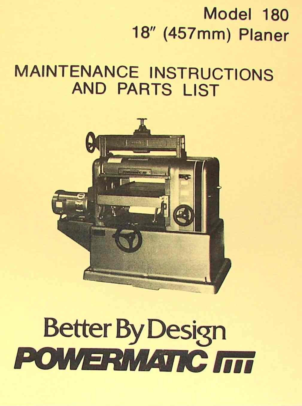
Figure 1: Cover of the Powermatic 180 18-inch Planer Operator and Parts Manual. This image displays the front cover of the instruction manual, featuring the product name and model number.
2. Safety Instructions
Operating any woodworking machinery, especially a planer, requires strict adherence to safety protocols to prevent injury. Always wear appropriate personal protective equipment (PPE), including safety glasses, hearing protection, and dust masks. Ensure the work area is clean, well-lit, and free from obstructions. Never operate the planer under the influence of drugs or alcohol. Disconnect power before performing any maintenance or adjustments.
- Read the entire manual: Understand all operating procedures and safety warnings.
- Use proper guarding: Ensure all safety guards are in place and functioning correctly.
- Secure workpiece: Always ensure the material being planed is properly supported and secured.
- Avoid loose clothing: Tie back long hair and avoid loose clothing or jewelry that could get caught in moving parts.
- Emergency stop: Know the location and operation of the emergency stop button.
3. Setup and Installation
Proper setup is critical for the performance and safety of your Powermatic 180 Planer. This section covers initial unpacking, assembly, electrical wiring, and basic adjustments.
3.1 Unpacking and Placement
Carefully remove the planer from its packaging. Inspect for any shipping damage. Place the planer on a stable, level surface capable of supporting its weight. Ensure adequate clearance around the machine for safe operation and material handling.
3.2 Electrical Wiring
Connect the planer to a dedicated electrical circuit as specified in the machine's electrical requirements. Consult a qualified electrician if you are unsure about wiring procedures. Ensure proper grounding to prevent electrical shock.
3.3 Initial Adjustments
Before first use, perform initial adjustments such as setting the infeed and outfeed tables, checking cutterhead alignment, and verifying feed roller pressure. Refer to the detailed diagrams in this manual for precise adjustment points.
4. Operating Instructions
This section outlines the procedures for operating the Powermatic 180 Planer, including preparing the material, feeding, and achieving desired results.
4.1 Knife Installation and Removal
Always disconnect power before changing knives. Follow the step-by-step instructions for safely removing dull knives and installing sharp ones. Ensure knives are properly seated and tightened to prevent them from dislodging during operation.
4.2 Jointing and Grinding Planer Knives
This manual provides detailed guidance on using the optional jointing and grinding attachment to maintain sharp planer knives. Proper jointing and grinding extend knife life and ensure a smooth finish on your material. Refer to the specific section for attachment installation and usage.
4.3 Planing Procedures
Set the desired depth of cut. Ensure the material is free of foreign objects (nails, screws). Feed the material smoothly and consistently through the planer. Avoid taking excessively deep cuts, which can strain the machine and result in poor finish quality.
5. Maintenance
Regular maintenance is essential for the longevity and optimal performance of your Powermatic 180 Planer. Always disconnect power before performing any maintenance.
5.1 Lubrication
Follow the lubrication schedule outlined in this manual. Use recommended lubricants for all moving parts, bearings, and feed mechanisms. Proper lubrication reduces wear and ensures smooth operation.
5.2 Cleaning
Regularly clean the planer to remove sawdust, chips, and resin buildup. Pay particular attention to the feed rollers, cutterhead area, and dust collection ports. A clean machine operates more efficiently and safely.
5.3 Inspection
Periodically inspect all belts, chains, electrical cords, and fasteners for wear or damage. Replace worn components immediately. Ensure all guards are secure and functional.
6. Troubleshooting
This section provides guidance on common issues you might encounter with your Powermatic 180 Planer and suggested solutions.
| Problem | Possible Cause | Solution |
|---|---|---|
| Poor surface finish (sniping, chatter) | Dull knives, incorrect table adjustment, excessive depth of cut | Sharpen/replace knives, adjust infeed/outfeed tables, reduce depth of cut |
| Material not feeding | Feed rollers dirty/worn, insufficient pressure, motor overload | Clean/replace rollers, adjust roller pressure, check motor for issues |
| Machine not starting | No power, emergency stop engaged, faulty switch | Check power supply, disengage E-stop, inspect switch |
For more complex issues or problems not listed, consult the detailed troubleshooting section within the full manual or contact Powermatic customer support.
7. Specifications
The Powermatic Model 180 is an 18-inch planer designed for precision woodworking. Key specifications include:
- Model: 180
- Planing Width: 18 inches
- Number of Pages in Manual: 32
- Language: English
For detailed electrical requirements, motor specifications, and dimensions, refer to the complete specifications section in the manual.
8. Parts and Diagrams
This manual includes comprehensive exploded view diagrams of all major components of the Powermatic 180 Planer. These diagrams are invaluable for identifying parts for replacement or assembly. Each diagram is accompanied by a parts list with corresponding numbers.
- Cutterhead Assembly: Detailed view of knives, gibs, and locking mechanisms.
- Feed Roller System: Exploded view of infeed and outfeed rollers, gears, and tensioning components.
- Table Adjustment Mechanism: Diagrams illustrating the components for raising and lowering the planer bed.
- Electrical Components: Wiring diagrams and component layout for switches, motor, and controls.
When ordering replacement parts, always refer to the specific part number provided in the diagrams to ensure compatibility.