1. Introduction
This document provides essential information for the proper installation, operation, and maintenance of the Allen Bradley 960187 4-Slot I/O Chassis, also identified as model 1771-A1B. This chassis is designed to house and connect various I/O modules within an industrial control system, facilitating communication and power distribution.
2. Product Overview
The Allen Bradley 1771-A1B is a robust 4-slot chassis designed for industrial environments. It provides the physical and electrical backplane for I/O modules, ensuring reliable operation of your control system.

Figure 2.1: Angled view of the Allen Bradley 1771-A1B 4-Slot I/O Chassis, showing the module slots and backplane.

Figure 2.2: Detailed view of the chassis backplane, highlighting the Allen-Bradley branding and part number 960187-01 A.
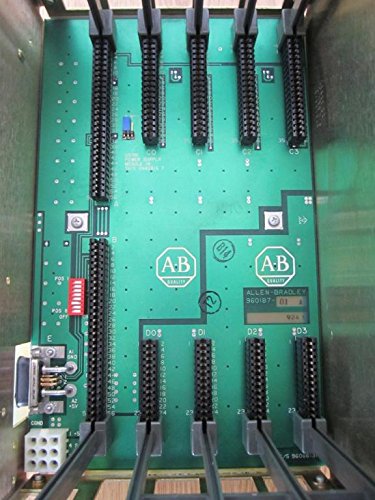
Figure 2.3: Top-down perspective of the 4-slot chassis, showing the arrangement of module connectors on the backplane.

Figure 2.4: Product label indicating 'CAT. NO. 1771-A1B 4 SLOT I/O CHASSIS' and electrical specifications. The barcode identifier is SD0WE5AI.

Figure 2.5: Bottom view of the chassis, showing the mounting points and structural components.

Figure 2.6: Close-up of the backplane circuit board, displaying the internal part number 960660-91.
3. Setup Instructions
Follow these steps for the correct installation of the 1771-A1B I/O Chassis:
- Mounting: Securely mount the chassis in a suitable industrial enclosure using appropriate hardware. Ensure adequate ventilation around the unit.
- Power Connection: Connect the chassis to a stable 5V DC power supply. Refer to the specifications for maximum current draw. The 5V backplane requires up to 16A at 5.25 VDC maximum, and the backplane memory line requires up to 0.5A at 5.25 VDC maximum.
- Module Installation: Carefully insert compatible Allen Bradley 1771 series I/O modules into the available 4 slots. Ensure each module is seated firmly and correctly.
- Wiring: Connect all necessary field wiring to the I/O modules according to your system's design and the specific module's documentation.
- System Integration: Integrate the chassis and its modules into your Programmable Logic Controller (PLC) system, following the PLC's programming and configuration guidelines.
4. Operating Principles
The 1771-A1B chassis serves as the foundational hardware for Allen Bradley 1771 series I/O modules. It provides the electrical connections and communication pathways (backplane) that allow the central processing unit (CPU) to interact with the I/O modules. Each slot in the chassis is designed to accept a specific I/O module, which then handles the interface with field devices such as sensors, actuators, and other control components. The backplane distributes power and data signals, enabling seamless operation of the entire I/O system.
5. Maintenance
Regular maintenance ensures the longevity and reliable operation of your 1771-A1B chassis:
- Visual Inspection: Periodically inspect the chassis for any signs of physical damage, corrosion, or loose connections.
- Cleaning: Keep the chassis and module slots free from dust and debris. Use a soft, dry cloth or compressed air for cleaning. Avoid using liquid cleaners directly on electronic components.
- Environmental Control: Ensure the operating environment adheres to the specified temperature and humidity ranges to prevent component degradation.
- Connection Integrity: Verify that all I/O modules are securely seated in their slots and that all wiring connections are tight.
6. Troubleshooting
If you encounter issues with the 1771-A1B chassis, consider the following troubleshooting steps:
- No Power: Check the power supply connections and ensure the 5V DC supply is within the specified voltage and current limits. Verify that the power source is active.
- Module Not Functioning: Ensure the I/O module is correctly seated in its slot. Verify that the module is compatible with the 1771-A1B chassis and the overall system.
- Communication Errors: Check the backplane connections and ensure there are no bent pins or foreign objects. Verify system configuration in the PLC software.
- Intermittent Operation: Inspect for loose wiring, environmental factors (temperature, vibration), or potential electromagnetic interference.
- Refer to Module Manuals: For issues specific to individual I/O modules, consult their respective instruction manuals.
7. Specifications
| Feature | Specification |
|---|---|
| Model Number | 1771-A1B |
| Part Number | 960187 |
| Number of Slots | 4 I/O Slots |
| Backplane Power (5V) | 16A @ 5.25 VDC Max. |
| Backplane Memory Line | 0.5A @ 5.25 VDC Max. |
| Dimensions (Approx.) | 8 x 8 x 14 inches |
| Weight (Approx.) | 5 Pounds |
| Manufacturer | Allen Bradley |
| Additional Identifier | 960660-91, SD0WE5AI |
8. Warranty Information
Specific warranty terms for the Allen Bradley 960187 4-Slot I/O Chassis (1771-A1B) are typically provided by the original manufacturer or the authorized seller at the time of purchase. Please refer to your purchase documentation or contact Allen-Bradley directly for detailed warranty coverage and conditions.
9. Support
For technical assistance, further documentation, or inquiries regarding the Allen Bradley 960187 4-Slot I/O Chassis (1771-A1B), please contact Allen-Bradley customer support or visit their official website. Ensure you have the model and part numbers readily available when seeking support.


