
1. Product Overview
The HHIP 3900-5508 is a BT50 Retention Knob designed for secure tool holding in machine spindles. This specific model features a 45-degree angle and is manufactured from SNCM 21 alloy steel, ensuring durability and strength. It is hardened to HRC 52-56° for optimal performance and longevity.
All dimensions of this retention knob conform to MAS 403 machine specifications, ensuring compatibility and reliable operation with appropriate machinery. The thread size is M24 X 3.0.

Figure 1: HHIP 3900-5508 BT50 Retention Knob. This image displays the retention knob, showing its threaded end, hexagonal body, and tapered pull stud end.
2. Key Features
- Material: Constructed from SNCM 21 alloy steel for high strength and wear resistance.
- Hardness: Heat-treated to HRC 52-56° for enhanced durability and performance under demanding conditions.
- Standard Compliance: All dimensions are manufactured in strict accordance with MAS 403 machine specifications, ensuring precise fit and function.
- Thread Specification: Features an M24 X 3.0 thread for secure attachment.
- Taper Angle: Designed with a 45-degree taper for compatibility with BT50 machine spindles.
3. Specifications
| Specification | Value |
|---|---|
| Model Number | 3900-5508 |
| Material | SNCM 21 Alloy Steel |
| Hardness | HRC 52-56° |
| Machine Taper Compatibility | BT50 |
| Retention Knob Angle | 45 Degrees |
| Thread Size | M24 X 3.0 |
| Overall Length (L) | 3.35 inches (85.09 mm) |
| Length L1 | 1.38 inches (35.05 mm) |
| Length L2 | 0.39 inches (9.91 mm) |
| Diameter D | 1.5 inches (38.1 mm) |
| Diameter D1 | 0.91 inches (23.11 mm) |
| Diameter D2 | 0.67 inches (17.02 mm) |
| Diameter D4 | 0.98 inches (24.89 mm) |
| Product Dimensions (Overall) | 15.24 x 15.24 x 15.24 cm |
| Item Weight | 0.32 Kilograms (315 g) |
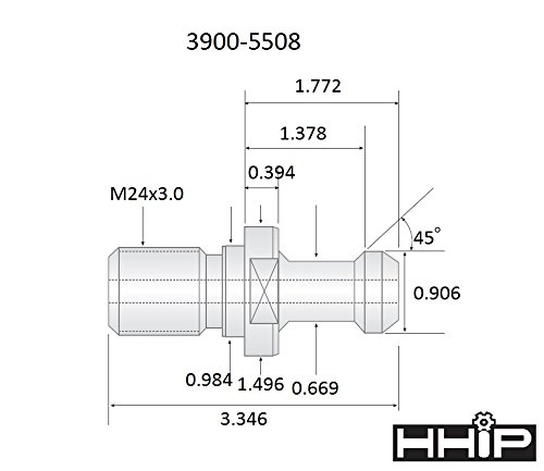
Figure 2: Detailed technical drawing of the 3900-5508 retention knob, illustrating key dimensions such as overall length, various diameters, and thread specifications. All measurements are in inches.
4. Installation and Setup
Proper installation of the retention knob is critical for safe and efficient machine operation. This component is designed to be threaded into the rear of a tool holder, allowing the machine's automatic tool changer (ATC) or manual drawbar to securely pull the tool holder into the spindle taper.
Installation Steps:
- Inspect Tool Holder: Before installation, ensure the threaded hole in the tool holder is clean and free of debris, chips, or burrs.
- Apply Thread Lubricant (Optional but Recommended): A small amount of anti-seize compound or thread lubricant can be applied to the threads of the retention knob to prevent galling and ensure smooth installation and removal.
- Thread the Knob: Carefully thread the HHIP 3900-5508 retention knob into the tool holder by hand until it is finger-tight. Ensure it threads smoothly without resistance.
- Torque to Specification: Using a torque wrench and the appropriate socket or wrench for the hexagonal body of the retention knob, tighten the knob to the tool holder manufacturer's specified torque. Do not overtighten, as this can damage the tool holder or the knob. Refer to your tool holder's manual for specific torque values.
- Verify Seating: After torquing, visually inspect the retention knob to ensure it is fully seated against the shoulder of the tool holder.
Important: Always use the correct retention knob for your specific tool holder and machine spindle taper (BT50 in this case). Mismatched components can lead to tool ejection, machine damage, or injury.
5. Operation
The HHIP 3900-5508 retention knob functions as the interface between the tool holder and the machine spindle's drawbar mechanism. Once installed onto a tool holder, the knob's pull stud end is engaged by the drawbar collets or grippers within the machine spindle.
Operational Principle:
- When a tool change is initiated, the machine's drawbar extends and grips the retention knob.
- The drawbar then retracts, pulling the tool holder firmly into the machine spindle's taper. This action creates a rigid connection, ensuring concentricity and stability during machining operations.
- The 45-degree angle of this BT50 retention knob is designed to match the internal taper of BT50 machine spindles, providing optimal contact and secure clamping.
- To release the tool, the drawbar mechanism is actuated to push the tool holder out of the spindle taper, allowing for tool changes.
Ensure that the retention knob is free from damage or wear before each use to maintain proper tool clamping force and prevent tool pull-out during high-speed or heavy-duty machining.
6. Maintenance and Safety
Regular inspection and proper maintenance of retention knobs are essential for safety and to prolong the life of your tooling and machine spindle. Retention knobs are subject to significant forces during tool changes and machining, making them prone to wear and fatigue.
Inspection Guidelines:
- Visual Inspection: Before each use, visually inspect the retention knob for any signs of wear, cracks, deformation, or damage, especially around the pull stud, threads, and shoulder.
- Thread Integrity: Check the threads for stripping, cross-threading, or burrs. Damaged threads can lead to improper seating or failure.
- Pull Stud Condition: Examine the pull stud for nicks, gouges, or excessive wear from the drawbar grippers. Significant wear can reduce clamping force.
- Shoulder Contact: Ensure the shoulder of the retention knob makes full and even contact with the tool holder. Uneven contact can indicate a bent knob or damaged tool holder.
- Magnetic Particle Inspection: For critical applications or if any damage is suspected, retention knobs should be periodically inspected using magnetic particle inspection to detect hairline cracks not visible to the naked eye.
Safety Precautions:
- Never Reuse Damaged Knobs: Retention knobs are not intended to last forever. If a knob shows any signs of damage, wear, or fatigue, it must be immediately replaced.
- Proper Torque: Always torque retention knobs to the tool holder manufacturer's specifications. Under-torquing can lead to tool pull-out, while over-torquing can cause the knob to stretch or break.
- Regular Replacement: Establish a regular replacement schedule for retention knobs based on usage intensity and machine type.
- Professional Inspection: Any retention knob that has been involved in a crash, or shows signs of unusual wear or damage, should be inspected by qualified maintenance personnel.
Failure to adhere to these inspection and safety guidelines can result in tool ejection, damage to the machine spindle, and serious injury to personnel.
7. Warranty and Support
Specific warranty details for the HHIP 3900-5508 BT50 Retention Knob are not provided in the product information. For warranty claims, technical support, or further inquiries, please contact the manufacturer, HHIP, or your authorized distributor.
It is recommended to retain your purchase receipt for any warranty-related communication.