1. Introduction
This manual provides detailed instructions for the installation, operation, and maintenance of your AIMS Power 2000 Watt 12V Pure Sine Inverter Charger. This unit combines an inverter, battery charger, and AC auto-transfer switch into a single system, designed for various applications including renewable energy systems, utility backup, RVs, and emergency vehicles. Please read this manual thoroughly before installation and use to ensure safe and efficient operation.
2. Safety Information
WARNING: Improper installation or operation can result in serious injury or death. Always follow safety guidelines.
- Ensure proper DC input voltage. Incorrect voltage may permanently damage the inverter and void the warranty.
- Do not block ventilation openings. The system is air-cooled, and a clearance of approximately 1 foot (30cm) is recommended around the unit for proper airflow.
- Always connect the battery with correct polarity. Reverse polarity will cause damage.
- Ensure all connections are secure to prevent loose connections, which can cause overheating and fire.
- This unit contains high voltage. Do not attempt to open or service the unit unless you are a qualified technician.
- Ground the unit properly according to local electrical codes.
3. Product Features
- Powerful Output: 2000W continuous pure sine wave power, with a 6000W surge capacity for 20 seconds.
- Integrated Charger: 70A smart battery charger with multi-stage charging for 8 different battery technologies, including lithium.
- Auto Transfer Switch: Seamless power transfer with approximately 10ms typical transfer time when utility or generator power is present.
- Comprehensive Protections: Includes overload, over-temperature, high voltage, low voltage, short circuit, and internally fused protection. Features low and high voltage alarms.
- Adjustable Charge Current: Charging current is adjustable from 0-100% for precise control over battery banks.
- Power Saver Mode: Designed to conserve battery power by entering a search mode when AC loads are low or infrequent.
- ETL Certified: Listed to UL 458 for land vehicles and marine crafts.
- Convenient Features: GFCI outlet, AC direct connect terminal block, charge current control dial, dip switches for priority settings, auto generator start functionality, and conformal coated components.
4. Components Overview
Familiarize yourself with the various components and connection points of the inverter charger.
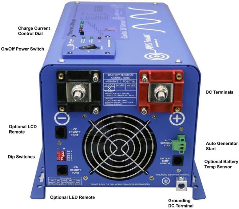
Figure 4.1: Rear Panel Connections and Controls
This image displays the rear panel of the AIMS Power Inverter Charger, highlighting key components such as the DC terminals (positive and negative), charge current control dial, on/off power switch, LCD remote port, dip switches, auto generator start terminal, optional battery temperature sensor port, and grounding DC terminal.

Figure 4.2: Detailed DC Terminal View
A closer look at the rear panel, emphasizing the large positive and negative battery terminal connectors for 12 VDC or 24 VDC systems. Important warnings regarding battery polarity and proper cable lug installation are visible.

Figure 4.3: AC Input and Output Connections
This image shows the side panel with the AC input and output connections, including the GFCI output receptacle and the hardwire terminal block for AC output. The ETL Listed mark is also visible.
4.1 Front Panel (Not explicitly shown in detail, but general controls)
- Power Switch: Controls the main power to the inverter.
- LED Indicators: Display operational status, fault conditions, and charging status.
4.2 Rear Panel (Refer to Figure 4.1 and 4.2)
- DC Terminals: Large terminals for connecting to the 12V battery bank. Ensure correct polarity (Positive + and Negative -).
- Grounding Terminal: For connecting the unit to an earth ground.
- LCD Remote Port: For connecting an optional LCD remote display.
- Dip Switches: Used to configure various settings such as battery type, charge voltage, and power saver mode.
- Charge Current Control Dial: Adjusts the battery charging current.
- Auto Generator Start Terminal: For connecting to a compatible generator for automatic starting.
- Battery Temp Sensor Port: For connecting an optional battery temperature sensor to optimize charging.
4.3 Side Panel (Refer to Figure 4.3)
- AC Input: Connection point for utility or generator AC power.
- AC Output: Connection point for AC loads.
- GFCI Output: A standard AC outlet with Ground Fault Circuit Interrupter protection.
- Circuit Breakers: Protect AC output circuits.
5. Setup and Installation
Proper installation is crucial for the safe and efficient operation of your inverter charger. If you are unsure about any step, consult a qualified electrician or technician.
5.1 Mounting the Unit
- Mount the inverter charger in a dry, well-ventilated area, away from direct sunlight, heat sources, and flammable materials.
- Ensure at least 1 foot (30cm) of clearance around the unit for proper airflow and cooling.
- Mount the unit securely to a stable surface using appropriate fasteners.
5.2 DC Battery Connections
- Battery Type: This unit is designed for 12V battery banks. Ensure your battery bank voltage matches the inverter's input voltage.
- Cable Sizing: Use appropriately sized cables for your battery connections to minimize voltage drop and ensure safety. Refer to electrical codes or a qualified professional for correct sizing.
- Connection Order:
- Connect the negative (-) battery cable to the negative (-) terminal on the inverter.
- Connect the positive (+) battery cable to the positive (+) terminal on the inverter.
- Connect the other end of the negative (-) cable to the negative (-) terminal of your battery bank.
- Connect the other end of the positive (+) cable to the positive (+) terminal of your battery bank.
- Secure Connections: Ensure all connections are tight and secure. Loose connections can cause arcing and overheating.
5.3 AC Wiring Connections
- AC Input: Connect the utility grid or generator AC power to the AC input terminals. Ensure the input voltage and frequency are compatible with the inverter charger.
- AC Output: Connect your AC loads to the AC output terminals or use the GFCI outlet.
- Grounding: Connect the grounding terminal of the inverter charger to a reliable earth ground.
- Circuit Protection: Ensure appropriate circuit breakers are installed on both AC input and output lines as per local electrical codes.
5.4 Remote Control and Sensor Connections (Optional)
- LCD Remote: If using an optional LCD remote, connect it to the designated LCD remote port on the rear panel.
- Battery Temperature Sensor: If using an optional battery temperature sensor, connect it to the battery temp sensor port and attach the sensor to the battery bank for accurate temperature compensation during charging.
- Auto Generator Start: Connect compatible auto generator start wiring to the designated terminal if this feature is desired.
6. Operating Instructions
6.1 Initial Power-Up
- After all connections are securely made and verified, switch on the DC power from the battery bank (if a disconnect switch is used).
- Turn the main power switch on the inverter charger to the "ON" position.
- Observe the LED indicators for normal operation. Refer to the troubleshooting section if any fault indicators illuminate.
6.2 Configuring Settings (Dip Switches)
The dip switches on the rear panel allow configuration of various operational parameters. Refer to the label on the unit or the full user manual for specific dip switch settings for battery type, charge voltage, and power saver mode. Ensure the unit is powered off before changing dip switch settings.
6.3 Inverter Operation
- When the unit is powered on and no AC input is present, the inverter will convert DC battery power to AC power for your connected loads.
- Power Saver Mode: This mode reduces idle power consumption. When activated via dip switch, the inverter will periodically "search" for a load. If a load greater than 50W is detected, the inverter will fully activate. If no load is detected, it returns to low-power search mode.
6.4 Charger Operation
- When external AC power (utility or generator) is connected to the AC input, the unit will automatically begin charging the battery bank.
- Charge Current Control: Use the charge current control dial to adjust the charging amperage. This is useful for smaller battery banks or when using a generator with limited output.
- Multi-Stage Charging: The charger employs a multi-stage charging process (bulk, absorption, float) to optimize battery health and lifespan.
6.5 AC Auto-Transfer Switch
- When external AC power is detected at the input, the unit will automatically transfer the AC loads from inverter power to the external AC source. This transfer typically occurs within 10 milliseconds.
- When external AC power is lost, the unit will automatically switch back to inverter power, drawing from the battery bank.
7. Maintenance
- Regular Inspection: Periodically inspect all wiring connections for tightness and corrosion. Clean any corrosion with a wire brush and baking soda solution.
- Ventilation: Ensure ventilation openings are clear of dust and debris. Clean with compressed air if necessary.
- Battery Maintenance: Follow the manufacturer's recommendations for your specific battery type. This may include checking electrolyte levels for flooded lead-acid batteries.
- Environmental Conditions: Keep the unit in a dry, cool environment. Avoid exposure to moisture, extreme temperatures, and corrosive fumes.
8. Troubleshooting
This section addresses common issues you might encounter. For more complex problems, contact AIMS Power technical support.
8.1 No AC Output from Inverter
- Check DC Connections: Ensure battery cables are securely connected and not corroded.
- Battery Voltage: Verify battery voltage is within the operating range (e.g., above low voltage cut-off). Charge batteries if low.
- Overload: Disconnect some AC loads. The inverter may have shut down due to an overload.
- Over-temperature: Ensure adequate ventilation. Allow the unit to cool down if it has overheated.
- Internal Fuse: If the unit is completely unresponsive, an internal fuse may have blown. This requires professional service.
8.2 Batteries Not Charging
- AC Input: Verify that external AC power is present and connected to the inverter's AC input.
- AC Input Breaker: Check if the AC input circuit breaker on the unit or external panel has tripped.
- Charge Current Dial: Ensure the charge current control dial is not set to zero.
- Battery Type Settings: Confirm dip switch settings match your battery type.
8.3 GFCI Outlet Trips Frequently
- Ground Fault: A ground fault may exist in the connected appliance or wiring. Disconnect appliances one by one to identify the faulty one.
- Overload: The connected load might be exceeding the GFCI outlet's rating.
9. Specifications
| Feature | Specification |
|---|---|
| Model | PICOGLF20W12V120V |
| Continuous Wattage | 2000 Watts |
| Surge Wattage | 6000 Watts (20 seconds) |
| DC Input Voltage | 12 Volts |
| AC Output Voltage | 120 Volts |
| Output Waveform | Pure Sine Wave |
| Battery Charger Current | 70 Amps (adjustable) |
| Transfer Time | Approximately 10ms |
| Dimensions | 21 x 13.8 x 12.4 inches |
| Item Weight | 55 pounds |
| Certifications | ETL Certified to UL 458 |
10. Warranty and Support
AIMS Power offers a 2-year warranty on this product. For technical assistance, warranty claims, or further information, please contact AIMS Power directly. All technical and warranty support is provided from their facility in Nevada, USA.
For additional resources, you may visit the AIMS Power Store on Amazon.


