1. Introduction
This manual provides detailed instructions for the safe operation and maintenance of the Proster Autoranging Multimeter 6000 Count, Model PSTTL334. This digital multimeter is designed for measuring AC/DC voltage, AC/DC current, resistance, capacitance, frequency, duty cycle, temperature, diode, and continuity. It also features Non-Contact Voltage (NCV) detection. Please read this manual thoroughly before use to ensure proper functionality and safety.
2. Safety Information
Adherence to safety precautions is crucial when operating any electrical testing equipment. This device complies with IEC61010 safety standards for electronic measuring instruments. Failure to follow these instructions may result in electric shock, fire, or damage to the meter.
- General Safety:
- Always ensure the meter is in good working condition before use. Inspect test leads for damage.
- Do not use the meter if it appears damaged or if the insulation on the test leads is compromised.
- Do not apply voltage exceeding the rated maximums (600V CAT IV, 1000V CAT III).
- Exercise extreme caution when working with voltages above 60V DC or 30V AC RMS, as these pose a shock hazard.
- Always disconnect power to the circuit under test before making resistance, capacitance, or diode measurements.
- Ensure the correct function is selected and the test leads are connected to the appropriate input jacks for the measurement being performed.
- Replace batteries when the low battery indicator appears to ensure accurate readings.
- Do not modify the meter. Repairs should only be performed by qualified service personnel.
- Symbols on the Meter:
- ▲ High Voltage: Indicates potential for high voltage.
- Δ Dual Insulation: Indicates double insulation for safety.
- ☀ Low Battery Indication: Indicates batteries need replacement.
3. Product Features
- 6000 Count True RMS Digital Multimeter: Provides accurate readings for non-sinusoidal waveforms.
- Auto/Manual Ranging: Automatically selects the appropriate measurement range or allows manual selection.
- Large Backlit LCD Display: Ensures clear visibility of readings in various lighting conditions.
- Non-Contact Voltage (NCV) Detection: For identifying live wires without direct contact, enhancing safety.
- Measurement Functions: AC/DC Voltage, AC/DC Current, Resistance, Capacitance, Frequency, Temperature, Diode Test, Continuity Test, Duty Cycle.
- Safety Ratings: CE certified, 600V CAT IV, 1000V CAT III, with double fuse protection.
- Data Hold Function: Freezes the displayed reading for convenient recording.
- Overload Protection: Integrated protection on all ranges to prevent damage to the meter.
- Protective Rubber Sleeve: Soft, non-slip orange rubber casing provides protection against impacts.
- Integrated Kickstand: Allows the meter to be propped at a 45° angle for hands-free viewing.
- Test Probe Slots: Convenient storage for test probes on the back of the meter.
- User-Friendly Design: Automatic polarity display, unit symbol display, flashlight, and auto power-off feature.
4. Package Contents
Verify that all items listed below are present in your package:
- 1 x Proster Digital Multimeter (Model PSTTL334)
- 1 x Pair of Test Leads (Red and Black)
- 1 x Pair of Alligator Clips (Red and Black, for banana plug connection)
- 1 x K-Type Temperature Probe
- 2 x 1.5V AAA Batteries (pre-installed or included separately)
- 1 x User's Manual

5. Setup
5.1 Battery Installation
The multimeter requires two 1.5V AAA batteries for operation. If the batteries are not pre-installed or need replacement, follow these steps:
- Ensure the multimeter is turned OFF.
- Locate the battery compartment on the back of the meter.
- Use a screwdriver to open the battery compartment cover.
- Insert the two AAA batteries, observing the correct polarity (+ and -) as indicated inside the compartment.
- Replace the battery compartment cover and secure it with the screw.


5.2 Connecting Test Leads
Always connect the test leads correctly for the desired measurement:
- The black test lead (negative) should always be connected to the COM (Common) input jack.
- For most voltage, resistance, capacitance, frequency, diode, and continuity measurements, connect the red test lead (positive) to the VΩmA input jack.
- For current measurements up to 600mA, connect the red test lead to the VΩmA input jack.
- For high current measurements (up to 10A), connect the red test lead to the 10A input jack.

6. Operating Instructions
Turn the rotary switch to the desired function. The meter features auto-ranging for most functions, simplifying operation.
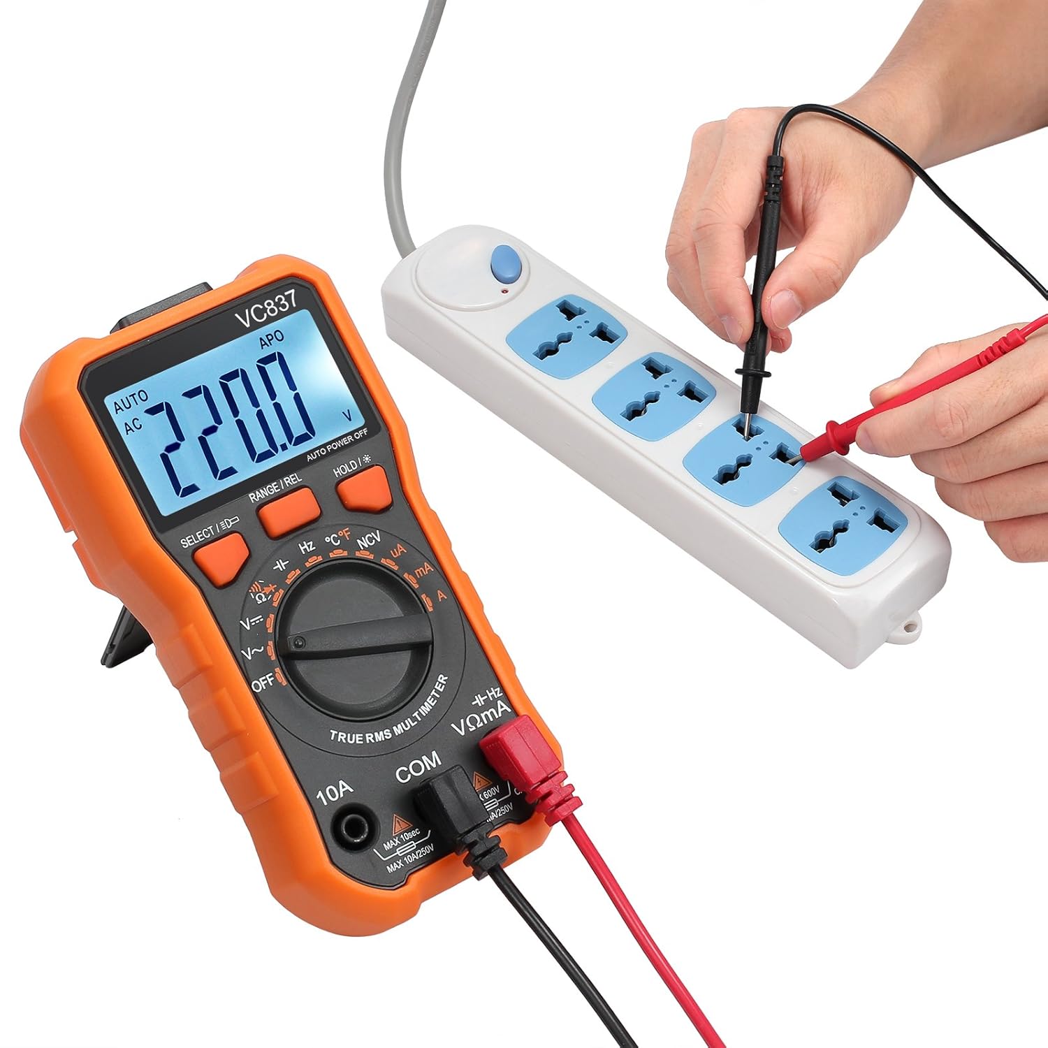
6.1 Measuring AC/DC Voltage (V∼ / V−)
- Connect the black test lead to the COM jack and the red test lead to the VΩmA jack.
- Turn the rotary switch to the V∼ (AC Voltage) or V− (DC Voltage) position.
- Touch the test probes to the circuit points where voltage is to be measured.
- Read the voltage value on the LCD display.

6.2 Measuring Resistance (Ω)
- Ensure the circuit is de-energized before measuring resistance.
- Connect the black test lead to the COM jack and the red test lead to the VΩmA jack.
- Turn the rotary switch to the Ω (Resistance) position.
- Touch the test probes across the component or circuit segment to be measured.
- Read the resistance value on the LCD display.
6.3 Continuity Test
- Ensure the circuit is de-energized.
- Connect the black test lead to the COM jack and the red test lead to the VΩmA jack.
- Turn the rotary switch to the ♫ (Continuity) position.
- Touch the test probes to the two points of the circuit or component.
- If continuity exists (low resistance), the meter will emit an audible beep. The display will show a low resistance value.

6.4 Non-Contact Voltage (NCV) Detection
- Turn the rotary switch to the NCV position.
- Move the top end of the multimeter near a conductor or outlet.
- If AC voltage is detected, the meter will beep and the NCV indicator light will illuminate. The frequency of beeps and light flashes increases with stronger voltage.
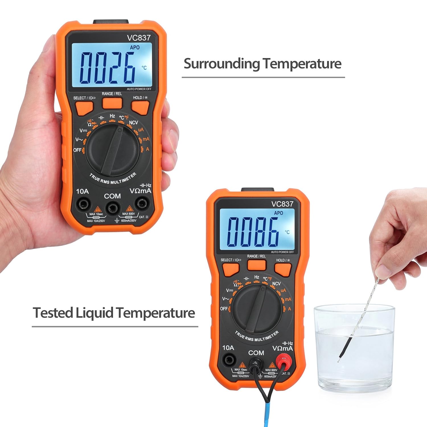
6.5 Temperature Measurement (°C/°F)
- Connect the K-type temperature probe to the VΩmA (positive) and COM (negative) input jacks, observing polarity.
- Turn the rotary switch to the °C/°F position.
- Place the tip of the temperature probe on or in the object whose temperature is to be measured.
- Read the temperature value on the LCD display. Use the "SELECT" button to switch between Celsius and Fahrenheit if available.
6.6 Other Functions (Current, Capacitance, Frequency, Diode)
For other measurement functions, connect the test leads as appropriate (refer to section 5.2) and select the corresponding position on the rotary switch. Use the SELECT button to cycle through sub-functions if a single rotary switch position covers multiple measurement types (e.g., AC/DC current, diode/continuity).
- Current (A∼ / A−): Ensure the meter is connected in series with the circuit. Use the 10A jack for high currents.
- Capacitance (F): Ensure capacitors are discharged before testing.
- Frequency (Hz): Connect across the signal source.
- Diode Test: Connect across the diode to measure forward voltage drop.
7. Maintenance
7.1 Cleaning
Wipe the meter casing with a damp cloth and mild detergent. Do not use abrasives or solvents. Keep the input jacks free from dust and debris.
7.2 Battery Replacement
Replace the batteries when the low battery indicator appears on the display. Refer to section 5.1 for detailed instructions.
7.3 Fuse Replacement
If the meter fails to measure current, the fuse may be blown. Fuse replacement should only be performed by qualified personnel. The meter uses double fuses for protection. Refer to the internal diagram for fuse specifications if replacement is necessary.
8. Troubleshooting
| Problem | Possible Cause | Solution |
|---|---|---|
| Meter does not power on. | Dead or incorrectly installed batteries. | Check battery polarity and replace batteries if necessary (refer to section 5.1). |
| No reading or "OL" (Overload) displayed. | Incorrect range selected (if manual ranging), open circuit, or value exceeds meter's maximum range. | Ensure correct function is selected. Check for open circuits. If in manual range, switch to a higher range or auto-range. |
| Inaccurate readings. | Low battery, damaged test leads, or external interference. | Replace batteries. Inspect test leads for damage. Move away from strong electromagnetic fields. |
| Current measurement fails. | Blown fuse. | Replace the fuse (refer to section 7.3). Ensure test leads are connected to the correct current input jack. |
9. Specifications
| Parameter | Value |
|---|---|
| Display | 6000 Counts, Backlit LCD |
| DC Voltage Range | Up to 1000V |
| AC Voltage Range | Up to 750V |
| DC Current Range | Up to 10A |
| AC Current Range | Up to 10A |
| Resistance Range | Up to 60MΩ |
| Capacitance Range | Up to 100mF |
| Frequency Range | Up to 10MHz |
| Temperature Range | -20°C to 1000°C (-4°F to 1832°F) |
| Diode Test | Yes |
| Continuity Test | Yes (with audible buzzer) |
| NCV (Non-Contact Voltage) | Yes |
| True RMS | Yes |
| Power Source | 2 x 1.5V AAA Batteries |
| Safety Rating | CAT III 1000V, CAT IV 600V |
| Dimensions | 5.51 x 2.83 x 1.45 inches (140 x 72 x 37 mm) |
| Weight | 12.63 ounces (358 grams) |
| Model Number | PSTTL334 |
10. Warranty and Support
Proster products are designed for reliability and performance. For warranty information or technical support, please refer to the contact details provided with your purchase documentation or visit the official Proster website. Keep your purchase receipt as proof of purchase for warranty claims.
For further assistance, you may visit the Proster Store on Amazon.


