1. Introduction
The Elektrobock RJ402 is a differential temperature switch designed to control a circulation pump based on temperature differences between two points. It activates the pump when a set temperature difference is detected and deactivates it when the difference falls below a specified hysteresis value. This device is ideal for optimizing energy usage in various heating and cooling systems.

Image 1: The Elektrobock RJ402 differential temperature switch unit with two included temperature sensors. The unit features control dials for differential temperature and hysteresis, along with indicator lights for power and relay status.
2. Product Overview
The RJ402 unit features intuitive controls and indicators for easy setup and monitoring:
- Function Switch: Selects between ON, OFF, and AUTO modes.
- Differential Temperature Dial (Diff T °C): Sets the temperature difference required to activate the relay.
- Hysteresis Dial (Hys °C): Sets the temperature reduction value for relay deactivation.
- PWR Indicator: Green LED indicates power supply.
- RE 1 Indicator: Red LED indicates relay status (active/inactive).
- Sensor Inputs: Connections for two NTC 10k temperature sensors.
- Relay Output: Potential-free contacts for controlling external devices.

Image 2: An illustration of the Elektrobock RJ402 mounted on a DIN rail, highlighting its operational modes: ON (relay always on), OFF (relay always off), and AUTO (relay activates based on set temperature difference). The text explains its function in controlling circulation pumps based on temperature differentials and hysteresis.
3. Installation and Wiring
The RJ402 is designed for DIN rail mounting. Proper installation and wiring are crucial for safe and effective operation. All electrical work should be performed by a qualified electrician.
3.1 Wiring Diagram
Refer to the detailed wiring diagram below for connecting the power supply, temperature sensors, and the controlled device (e.g., a pump).

Image 3: Detailed technical diagram showing the wiring connections for the Elektrobock RJ402. It labels the terminals for Temperature Sensor 1, Temperature Sensor 2, Function Switch, Power Supply, and Relay Contact. It also indicates the adjustment dials for differential temperature (relay activation) and hysteresis (relay deactivation), along with Live (L), Neutral (N), and Load (M) connections.
3.2 Connection Steps
- Power Supply: Connect the 230 V AC power supply to the designated L (Live) and N (Neutral) terminals.
- Temperature Sensors: Connect Temperature Sensor 1 and Temperature Sensor 2 to their respective terminals. Ensure correct polarity if specified by the sensor type.
- Relay Output: Connect the device to be controlled (e.g., a circulation pump) to the potential-free relay contacts. The relay acts as a switch, so connect the load's power line through these contacts.
- Mounting: Securely mount the RJ402 unit onto a standard DIN rail.
4. Operation
The RJ402 offers three operational modes controlled by the function switch:
- ON: The relay is constantly switched on, regardless of temperature differences.
- OFF: The relay is constantly switched off, regardless of temperature differences.
- AUTO: The relay operates based on the set differential temperature and hysteresis values. This is the primary operational mode for automatic control.
4.1 Setting Differential Temperature (Diff T °C)
Use the upper dial to set the desired temperature difference between Sensor 1 and Sensor 2 that will activate the relay. The adjustable range is typically +20 °C to +80 °C.
4.2 Setting Hysteresis (Hys °C)
Use the lower dial to set the hysteresis value. This value determines how much the temperature difference must decrease below the activation point before the relay deactivates. The adjustable range is typically +2 °C to +35 °C. Hysteresis prevents rapid cycling (on/off) of the controlled device.
5. Application Examples
The Elektrobock RJ402 is versatile and can be used in various temperature-controlled systems.
5.1 Automatic Pump Activation in a Solar Heating System
In a solar heating system, the RJ402 can control a pump to transfer heat from solar collectors to a water storage tank.

Image 4: Diagram illustrating Application Example 1: Automatic pump activation in a solar heating system. Sensor 1 is placed at the solar collector, and Sensor 2 is at the water tank. The RJ402 controls the pump to transfer heat when the temperature difference is met.
5.2 Automatic Hot Water Tank Charging
The RJ402 can manage the charging of a hot water tank from a heat source (e.g., boiler or wood stove) by activating a circulation pump.

Image 5: Diagram illustrating Application Example 2: Automatic hot water tank charging. Sensor 1 is placed at the heat source (e.g., boiler), and Sensor 2 is at the hot water tank. The RJ402 controls the pump to charge the tank when the temperature difference is met.

Image 6: An image of a house with solar panels, illustrating the environmental and economic benefits of using solutions like the RJ402 in solar heating systems.
6. Technical Specifications
| Parameter | Value |
|---|---|
| Operating Voltage | 230 V AC / 50 Hz |
| Power Consumption | < 0.5 Watt |
| Operating Temperature | 0 °C to +50 °C |
| Control Range (Differential Temperature) | +20 °C to +80 °C |
| Hysteresis Range | +2 °C to +35 °C |
| Output | Relay, max. 5 A / 250 V AC |
| Protection Class | IP20 |
| Contact Type | Changeover contact |
| Temperature Sensors | 2 x NTC 10k (1.5 m length, max. 6.5 mm diameter) |
| Dimensions (L x W x H) | 8.7 x 5.2 x 6 cm (approx. 90 x 53 x 58 mm) |
| Weight | 222 grams (approx. 137 g for unit only) |
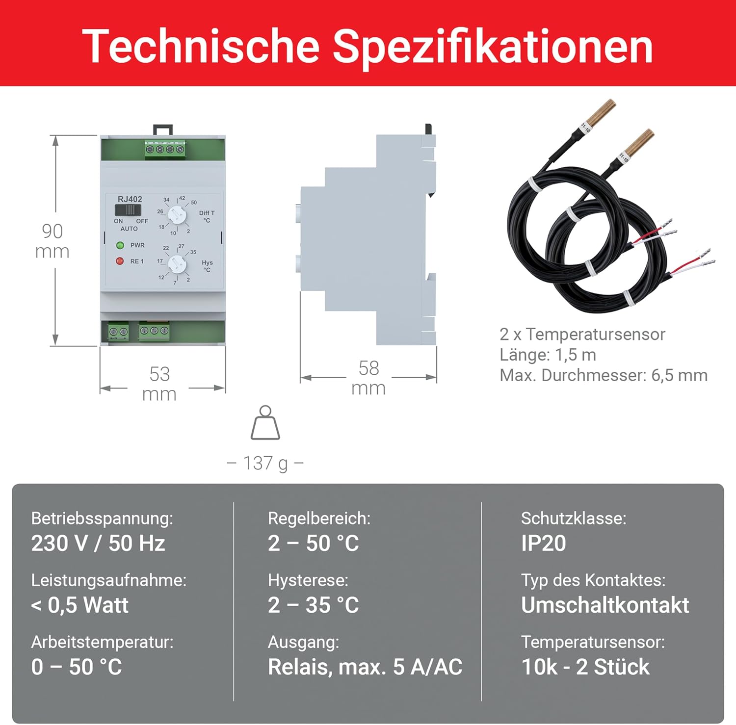
Image 7: An image detailing the technical specifications and dimensions of the Elektrobock RJ402. It shows the physical dimensions (90x53x58 mm) and weight (137g), along with specifications for the two 1.5m temperature sensors. Electrical parameters include 230V/50Hz operating voltage, <0.5W power consumption, 0-50°C operating temperature, 2-50°C control range, 2-35°C hysteresis, 5A/AC relay output, IP20 protection, and changeover contact type.
7. Safety Information
Always observe the following safety precautions:
- Disconnect power before installation, wiring, or maintenance.
- Ensure all wiring complies with local electrical codes and regulations.
- Do not expose the device to moisture or extreme temperatures outside its operating range.
- The device is designed for indoor use only (IP20 protection).
- Do not attempt to open or repair the device yourself. Refer to qualified personnel.
8. Maintenance and Troubleshooting
8.1 Maintenance
The Elektrobock RJ402 is designed for maintenance-free operation. Periodically check connections for tightness and ensure the unit is free from dust and debris. Clean the exterior with a dry, soft cloth if necessary.
8.2 Troubleshooting
- Device not powering on: Check the 230 V AC power supply connection. Ensure the power source is active.
- Relay not activating/deactivating:
- Verify the function switch is set to AUTO.
- Check sensor connections and ensure they are correctly placed to measure the desired temperatures.
- Confirm that the differential temperature and hysteresis settings are appropriate for your application.
- Ensure the temperature difference between sensors meets the set activation criteria.
- Inaccurate temperature readings: Check sensor placement and ensure they are not damaged or exposed to external interference.
If issues persist, consult a qualified technician or contact Elektrobock customer support.
9. Warranty and Support
For warranty information, technical support, or service inquiries, please refer to the documentation provided with your purchase or visit the official Elektrobock website. Keep your proof of purchase for warranty claims.


