
Ford F-150
Contents
2005 Ford F-150 Wiring Diagrams Service Repair Shop Manual
Official Electrical Wiring Diagrams for the 2005 Ford F-150 Truck
Introduction
This manual provides comprehensive electrical wiring diagrams for the 2005 Ford F-150 truck. It is an essential resource for diagnosing, servicing, and repairing the vehicle's electrical systems. Published by Ford, this manual contains the same detailed information used by Ford mechanics and technicians, ensuring accuracy and reliability for all electrical work.
The content includes a vast amount of information and illustrations, covering various electrical components and circuits without missing pages. Step-by-step instructions, exploded illustrations, and detailed diagrams are provided to guide users through complex electrical procedures.
Manual Overview and Structure
The 2005 Ford F-150 Wiring Diagrams Manual is organized to facilitate easy navigation and quick access to specific electrical information. It typically follows a logical flow, starting with general information and progressing to detailed circuit diagrams for various vehicle systems.
Key sections often include:
- System Wiring Diagrams: Dedicated sections for engine controls, transmission, chassis, body, accessories, and more.
- Component Locations: Diagrams showing the physical location of electrical components within the vehicle.
- Connector Views: Illustrations of electrical connectors, including pin-outs and wire colors.
- Ground Point Locations: Details on where various ground points are located.
- Splice Locations: Information on wire splices within the harness.
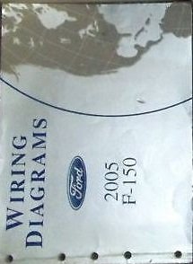
Image: Front cover of the 2005 Ford F-150 Wiring Diagrams Service Repair Shop Manual. The cover displays "WIRING DIAGRAMS", the Ford logo, and "2005 F-150".
Using the Diagrams
To effectively use this manual, familiarize yourself with the standard conventions and symbols employed in automotive wiring diagrams. Each diagram is designed to provide a clear representation of electrical circuits, showing components, wire paths, and connections.
- Tracing Circuits: Follow the lines representing wires from power sources through components to ground. Note wire colors and sizes, which are often indicated.
- Identifying Components: Components are typically represented by standardized symbols. Refer to the manual's legend or symbol guide for identification.
- Understanding Connectors: Connector views show the pin configuration, which is crucial for testing continuity or making repairs.
Symbols and Abbreviations
The manual includes a comprehensive section detailing the symbols and abbreviations used throughout the wiring diagrams. Understanding these is critical for accurate interpretation.
| Symbol | Description |
|---|---|
| —▶— | Fuse |
| —○— | Switch (General) |
| —⊗— | Lamp/Bulb |
| —∩— | Resistor |
| —∪— | Inductor/Coil |
| ——∣∣—— | Capacitor |
| ⊥ | Ground |
Common abbreviations include: B+ (Battery Positive), GND (Ground), IGN (Ignition), ECM (Engine Control Module), PCM (Powertrain Control Module), ABS (Anti-lock Braking System), etc. A full list is provided within the manual.
Troubleshooting with Diagrams
The wiring diagrams are indispensable for electrical troubleshooting. By following the circuit paths, you can pinpoint potential issues such as open circuits, short circuits, or faulty components.
- Identify the Affected Circuit: Locate the relevant wiring diagram for the system experiencing a fault.
- Check Power and Ground: Verify that power is reaching the component and that the ground path is intact.
- Inspect Connectors and Splices: Use the diagrams to locate and inspect connectors and splices for corrosion, damage, or loose connections.
- Test Components: The diagrams often provide context for testing individual components within the circuit.
- Trace Wires: Follow the wire paths to identify breaks or shorts.
Maintenance Information
While primarily a repair manual, the wiring diagrams also support electrical system maintenance. Understanding the electrical layout helps in tasks such as:
- Fuse Replacement: Identifying the correct fuse for a specific circuit.
- Accessory Installation: Safely integrating aftermarket accessories by understanding existing circuits and available power sources.
- Preventive Checks: Knowing where to inspect wiring harnesses for wear or damage.
Specifications
This manual provides detailed specifications related to the electrical system of the 2005 Ford F-150. While specific values are contained within the manual itself, typical specifications covered include:
- Wire Gauge Sizes: Indication of wire thickness for various circuits.
- Fuse and Relay Ratings: Correct amperage for fuses and specifications for relays.
- Component Resistance Values: Expected resistance for certain sensors or actuators.
- Voltage Drop Specifications: Acceptable voltage drops across circuits.
Refer to the specific sections within the manual for precise values and tolerances.
Warranty and Support
This 2005 Ford F-150 Wiring Diagrams Service Repair Shop Manual is an official publication by Ford. As a printed manual, it is typically covered by standard retail return policies if purchased new and found to be defective or incomplete upon receipt.
For questions regarding the content or specific diagrams within the manual, it is recommended to consult with a certified Ford technician or refer to official Ford service information resources. Direct support for the manual's content is generally not provided by the publisher to individual end-users, as it is intended for professional and informed use.
For issues related to the purchase or condition of the physical manual, please contact your retailer or the point of purchase.
Ask a question about this manual
Ask about setup, troubleshooting, compatibility, parts, safety, or missing instructions. Manuals+ will review the question and use this page’s manual context to help answer it.