1. Introduction
This manual provides essential information for the safe and effective operation of your OWON SDS6062 Digital Storage Oscilloscope. Please read this manual thoroughly before using the device to ensure proper setup, operation, and maintenance. The SDS6062 is a 2-channel oscilloscope featuring a 60 MHz bandwidth, 500 MS/s sample rate, and a 10M record length, designed for precise electrical signal analysis.
2. Safety Information
Always observe the following safety precautions to prevent injury and avoid damage to the instrument or any connected products. Read these instructions carefully before operation.
- Power Source: Use only the power adapter supplied with the instrument. Ensure the voltage matches your local power supply.
- Grounding: The oscilloscope must be properly grounded to prevent electric shock.
- Probe Safety: Do not connect the probe ground lead to a point where a voltage greater than 30V RMS or 42.4V peak is present.
- Environment: Operate the device in a well-ventilated area, away from moisture, dust, and direct sunlight. Avoid operating in explosive atmospheres.
- Maintenance: Refer all servicing to qualified service personnel. Do not attempt to repair the unit yourself.
3. Package Contents
Verify that all items listed below are present in your package. If any items are missing or damaged, contact your supplier.
- OWON SDS6062 Digital Storage Oscilloscope Unit
- 2 x Oscilloscope Probes
- 1 x Power Cord
- 1 x Probe Adjust Pen
- 1 x USB Data Cable
- 1 x Software CD
- 1 x User's Manual (this document)
4. Product Overview
The OWON SDS6062 is a compact and powerful digital storage oscilloscope. It features an 8-inch (800x600) color TFT-LCD screen for clear waveform display and an intuitive control panel for easy operation. Key features include its 60 MHz bandwidth, 500 MS/s real-time sample rate, and 10M record length, making it suitable for a wide range of applications.
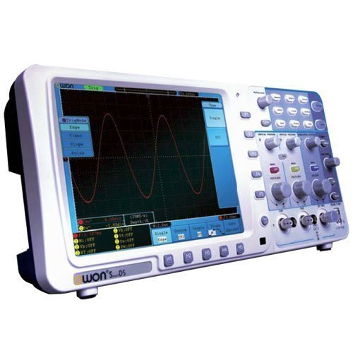
Figure 4.1: Front view of the OWON SDS6062 Digital Storage Oscilloscope, showing the display, control knobs, and function buttons.
4.1 Front Panel Controls
The front panel includes the main display, vertical controls (VOLTS/DIV, position), horizontal controls (SEC/DIV, position), trigger controls, and various function buttons for menu navigation, measurement, and utility settings.
4.2 Rear Panel Connections
The rear panel provides connectivity options including the power input, USB host and device ports, LAN port for network connectivity, and a VGA port for external display output.
5. Setup
Follow these steps to set up your OWON SDS6062 oscilloscope for initial use.
5.1 Connecting Power
- Ensure the oscilloscope is turned off.
- Connect the supplied power cord to the power input on the rear panel of the oscilloscope.
- Plug the other end of the power cord into a grounded AC power outlet.
5.2 Connecting Probes
- Align the BNC connector of the probe with the CH1 or CH2 input on the front panel.
- Push and twist the connector clockwise until it locks into place.
- Attach the probe ground clip to the ground terminal of the circuit under test.
- Set the probe attenuation switch (e.g., 1X or 10X) to match the setting on the oscilloscope's input channel menu.
5.3 Initial Power-On
- Press the power button located on the front panel.
- The oscilloscope will perform a self-test and display the startup screen.
- After startup, it is recommended to perform a probe compensation adjustment (refer to Section 7.3).
6. Operating the Oscilloscope
This section covers basic operation and common functions of the SDS6062.
6.1 Basic Measurements
To display a signal:
- Connect a signal source to CH1 or CH2 using a probe.
- Press the AUTOSET button. The oscilloscope will automatically adjust vertical, horizontal, and trigger settings to display a stable waveform.
- Adjust the VOLTS/DIV knob to change the vertical scale (voltage per division).
- Adjust the SEC/DIV knob to change the horizontal scale (time per division).
- Use the vertical and horizontal POSITION knobs to move the waveform on the screen.
6.2 Trigger System
The trigger system stabilizes repetitive waveforms and captures single-shot events.
- Trigger Level: Use the TRIGGER LEVEL knob to set the voltage level at which the trigger occurs.
- Trigger Mode: Access the trigger menu to select modes like Edge, Pulse, Video, or Slope.
- Trigger Source: Select the input channel (CH1, CH2, EXT, AC Line) that will be used for triggering.
6.3 Measurement Functions
The SDS6062 offers various automatic measurement functions.
- Press the MEASURE button to display the measurement menu.
- Select desired measurements such as Vpp, Vmax, Vmin, Freq, Period, Rise Time, etc.
6.4 Connectivity (LAN and VGA)
- LAN: Connect an Ethernet cable to the LAN port on the rear panel to connect the oscilloscope to a network. This allows for remote control and data transfer using compatible software.
- VGA: Use the VGA port to connect an external monitor or projector for larger display of waveforms, useful for presentations or collaborative work.
7. Maintenance
Proper maintenance ensures the longevity and accuracy of your oscilloscope.
7.1 Cleaning
Clean the instrument regularly with a soft, damp cloth. Do not use abrasive cleaners or solvents that could damage the casing or screen. Ensure the device is powered off and unplugged before cleaning.
7.2 Storage
When not in use, store the oscilloscope in a dry, dust-free environment, away from extreme temperatures and direct sunlight. Use the original packaging or a suitable carrying case for protection during transport.
7.3 Probe Compensation Adjustment
Probe compensation should be adjusted to match the oscilloscope's input characteristics. This ensures accurate measurements.
- Connect the probe to CH1 and attach the probe tip to the probe compensation output (usually a square wave test point on the front panel).
- Attach the probe ground clip to the ground terminal.
- Press AUTOSET.
- Use the supplied probe adjust pen to turn the trimmer screw on the probe until the square wave displayed on the screen has flat top and bottom edges (no overshoot or undershoot).
8. Troubleshooting
This section provides solutions to common issues you might encounter.
- No Display: Check power connection, ensure the power button is pressed. Adjust screen brightness if necessary.
- No Waveform: Verify probe connection to the input channel and the circuit under test. Ensure the signal source is active. Press AUTOSET. Check vertical and horizontal scale settings.
- Unstable Waveform: Adjust the trigger level. Check trigger mode and source settings. Ensure the signal is within the oscilloscope's bandwidth.
- Inaccurate Measurements: Perform probe compensation adjustment (Section 7.3). Ensure probe attenuation settings match the oscilloscope.
- Device Not Responding: Try restarting the oscilloscope. If the issue persists, contact technical support.
9. Specifications
Technical specifications for the OWON SDS6062 Digital Storage Oscilloscope.
| Parameter | Specification |
|---|---|
| Model Number | SDS6062 |
| Bandwidth | 60 MHz |
| Channels | 2 + 1 (External Trigger) |
| Sample Rate (Real-time) | 500 MS/s |
| Record Length | 10M points |
| Display | 8-inch Color TFT-LCD (800x600) |
| Interface | USB Host, USB Device, LAN, VGA |
| AutoScale Function | Yes |
| Manufacturer | OWON |
10. Warranty and Support
OWON products are designed for reliability and performance. For warranty information, please refer to the warranty card included with your product or visit the official OWON website. For technical support, troubleshooting assistance, or service inquiries, please contact your local OWON distributor or the OWON customer service department. Keep your purchase receipt as proof of purchase for warranty claims.


