Introduction
This manual provides essential information for the proper installation, operation, and maintenance of the Allen-Bradley 1750-EC Analog Timer Module. Please read this manual thoroughly before using the module to ensure safe and efficient operation.
Product Overview
The Allen-Bradley 1750-EC is an analog timer circuit board module designed for industrial applications. It is identified by part number 1750-EC and features various electronic components on a printed circuit board.

Figure 1: Top view of the Allen Bradley 1750-EC Analog Timer Module, showing the main circuit board with various integrated circuits, resistors, capacitors, and the edge connector.

Figure 2: Close-up view of the label indicating "CAT. NO. 1750- EC" on the module's edge connector housing, confirming the model identification.

Figure 3: Bottom view of the module's connector pins, showing the "TIMER" designation printed on the housing, indicating its primary function.

Figure 4: Detailed view of the yellow barcode label on the module's underside, displaying the identifier "RAC0156320". This number can be used for tracking and inventory purposes. For more information, refer to RAC0156320 product details.
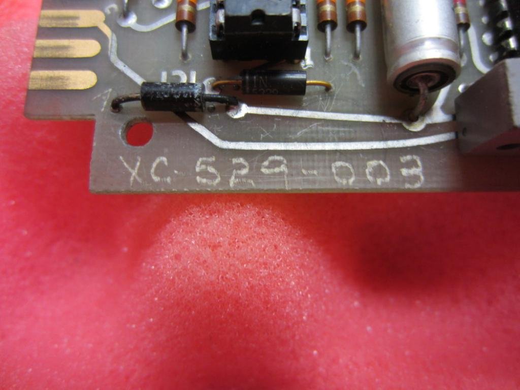
Figure 5: Close-up of the "XC 529-003" marking etched onto the circuit board, likely a manufacturing or design revision identifier.

Figure 6: Another perspective of the top side of the 1750-EC module, providing a comprehensive view of its components and layout.

Figure 7: View of the solder side (bottom) of the 1750-EC circuit board, revealing the intricate network of conductive traces and solder points.
Specifications
| Attribute | Value |
|---|---|
| Model Number | 1750-EC |
| Manufacturer | Allen Bradley |
| Product Type | Analog Timer Circuit Board Module |
| Connectivity Protocol | X-10 |
| Unit Count | 1.0 Count |
| Number of Items | 1 |
| Date First Available | November 26, 2015 |
Installation and Setup
The Allen-Bradley 1750-EC Analog Timer Module is designed for integration into compatible industrial control systems. Due to the specialized nature of this module, installation should only be performed by qualified personnel familiar with industrial electrical systems and safety procedures.
Safety Precautions:
- Ensure all power to the system is disconnected and locked out before beginning installation.
- Verify proper grounding of the system.
- Handle the module by its edges to avoid damaging electronic components or static discharge.
- Refer to the overall system's wiring diagrams and documentation for specific connection points.
Installation Steps:
- Identify the appropriate slot or connector within your control system for the 1750-EC module.
- Carefully align the module's edge connector pins with the system's receptacle.
- Gently but firmly insert the module until it is fully seated. Do not force the module.
- Secure the module if retention mechanisms (e.g., screws, latches) are present.
- Once installed, re-verify all connections before restoring power.
Operation
The 1750-EC Analog Timer Module functions as a component within a larger control system. Its specific operational parameters and programming will depend on the system it is integrated into. As an analog timer, it typically provides timing functions based on analog input signals or generates analog output signals for timing-related control.
Key Operational Aspects:
- Timing Range: Refer to the system's programming interface or associated documentation for the configurable timing ranges and resolutions.
- Input/Output Signals: Understand the analog input signals (e.g., voltage, current) that trigger or control the timer, and the analog output signals it produces.
- Programming: The module's timing logic and parameters are typically configured via the host PLC or control system's software. Consult the system's programming manual for details on configuring timer functions.
- Indicators: Observe any LEDs or diagnostic indicators on the module or host system that provide status information (e.g., power, active timer, error).
For detailed operational procedures, consult the documentation specific to the control system or PLC with which this module is used.
Maintenance
The Allen-Bradley 1750-EC Analog Timer Module is a robust electronic component designed for long-term reliability. Routine maintenance is generally minimal but crucial for optimal performance and longevity.
General Maintenance Guidelines:
- Cleaning: Periodically inspect the module for dust, dirt, or debris accumulation. If cleaning is necessary, disconnect power and use a soft, dry, lint-free cloth. Avoid using solvents or abrasive cleaners.
- Environmental Conditions: Ensure the operating environment remains within the specified temperature and humidity ranges to prevent component degradation.
- Connection Integrity: Regularly check that the module is securely seated in its slot and that all connections are firm. Loose connections can lead to intermittent operation or failure.
- Visual Inspection: Conduct periodic visual inspections for any signs of physical damage, discoloration, or bulging components, which may indicate a fault.
Note: This module is a sealed electronic component. Do not attempt to open or repair the module yourself, as this will void any potential warranty and may cause further damage or personal injury. Refer all repairs to authorized service personnel.
Troubleshooting
Troubleshooting the 1750-EC Analog Timer Module typically involves diagnosing issues within the larger control system. Since the module itself is a circuit board, direct user-level troubleshooting is limited. However, general steps can help identify potential problems.
Common Issues and Solutions:
| Problem | Possible Cause | Action |
|---|---|---|
| Module not recognized by system | Improper seating; power issue; system configuration error |
|
| Incorrect timing operation | Incorrect programming; faulty input/output; module malfunction |
|
| No response from module | No power; damaged module; communication error |
|
If troubleshooting steps do not resolve the issue, contact Allen-Bradley technical support or a qualified service technician.
Warranty and Support
Specific warranty terms for the Allen-Bradley 1750-EC Analog Timer Module are typically provided at the point of purchase or through official Allen-Bradley documentation. As this module is listed as "Obsolete" in some descriptions, warranty coverage may be limited or no longer applicable. It is recommended to verify warranty status with your supplier or Allen-Bradley directly.
For technical support, documentation, or service inquiries, please refer to the official Allen-Bradley (Rockwell Automation) website or contact their customer service. Provide the model number (1750-EC) and any other relevant identifiers (e.g., RAC0156320, XC 529-003) when seeking assistance.
Official Product Videos
There are no official product videos provided by the seller for the Allen-Bradley 1750-EC Analog Timer Module at this time.


