
1. Introduction
This manual provides essential information for the installation, operation, maintenance, and troubleshooting of the Allied Telesys AT-X930-28GTX Layer 3 Switch. The AT-X930-28GTX is a high-performance network switch designed for demanding enterprise and data center environments, offering advanced Layer 3+ features, Gigabit Ethernet connectivity, and SFP+ uplink ports.
Please read this manual thoroughly before installing or operating the device to ensure proper functionality and to prevent damage.
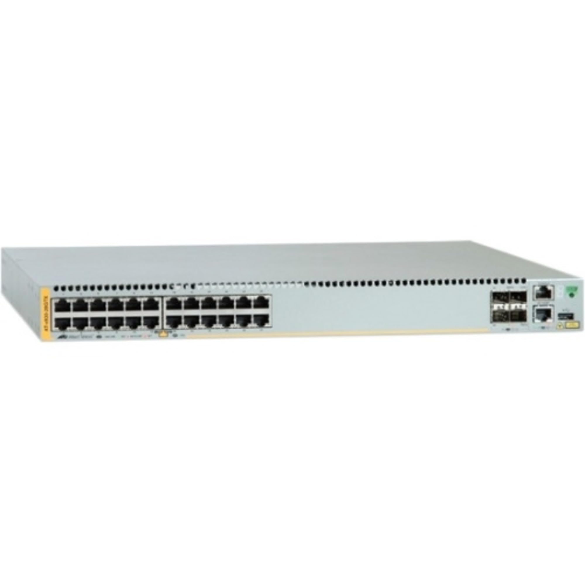
Figure 1: Allied Telesys AT-X930-28GTX Layer 3 Switch. This image displays the general appearance of the network switch, highlighting its compact form factor and port layout.
2. Safety Information
Observe the following safety precautions to prevent injury and damage to the equipment:
- Electrical Safety: Ensure the power source matches the voltage requirements of the switch. Use only the provided power cords. Do not operate the device with damaged power cords or plugs.
- Grounding: The switch must be properly grounded to prevent electrical shock.
- Ventilation: Ensure adequate airflow around the device. Do not block ventilation openings. Maintain proper clearance for heat dissipation.
- Environment: Operate the switch in a clean, dry environment within the specified temperature and humidity ranges. Avoid exposure to direct sunlight, water, or excessive dust.
- Handling: The switch is heavy (approximately 16 kg). Use proper lifting techniques or assistance when moving the unit.
- Servicing: Refer all servicing to qualified service personnel. Do not attempt to open or repair the device yourself.
3. Package Contents
Verify that your package contains the following items. If any item is missing or damaged, contact your vendor immediately.
- Allied Telesys AT-X930-28GTX Layer 3 Switch
- AC Power Cord(s)
- Rack Mount Kit (brackets, screws)
- Console Cable (RJ-45 to DB-9)
- Quick Start Guide
- Safety and Regulatory Information
4. Physical Description
4.1. Front Panel
The front panel of the AT-X930-28GTX features the primary network interfaces and status indicators:
- 24 x 10/100/1000BASE-T Gigabit Ethernet Ports: These RJ-45 ports provide standard copper connectivity for network devices. Each port has associated Link/Activity and Speed LEDs.
- 4 x 10 Gigabit SFP+ Ports: These ports support 10 Gigabit Ethernet fiber transceivers for high-speed uplinks or stacking.
- System Status LEDs: Indicators for Power, System Status, and Fan Status provide quick visual diagnostics of the switch's operational state.
- Console Port: An RJ-45 serial console port for local management and initial configuration.
4.2. Rear Panel
The rear panel houses power inputs and expansion slots:
- Modular Power Supply Slots: Two slots for redundant, hot-swappable AC or DC power supply units (PSUs). The switch supports internal redundant modular PSUs.
- QSFP Expansion Module Slot: A dedicated slot for an optional QSFP expansion module, providing additional high-speed connectivity options.
- Grounding Screw: A terminal for connecting the chassis to an earth ground.
5. Setup
5.1. Installation
- Rack Mounting: Attach the provided rack-mount brackets to the sides of the switch using the included screws. Secure the switch into a standard 19-inch equipment rack. Ensure proper ventilation space (at least 10 cm) around the front and rear panels.
- Power Connection: Insert the power supply units (if not pre-installed) into the modular slots on the rear panel. Connect the AC power cords to the PSUs and then to a grounded power outlet. For redundancy, connect each PSU to an independent power source.
- Grounding: Connect a grounding wire from the grounding screw on the rear panel to a reliable earth ground.
5.2. Initial Configuration
- Console Connection: Connect the console cable from your management workstation's serial port to the RJ-45 console port on the switch's front panel.
- Terminal Emulator: Open a terminal emulation program (e.g., PuTTY, Tera Term) on your workstation. Configure the serial port settings: 9600 bps, 8 data bits, no parity, 1 stop bit, no flow control.
- Power On: Power on the switch. Observe the boot sequence in the terminal window.
- Login: At the login prompt, enter the default username and password (refer to the Quick Start Guide for default credentials).
- Basic Configuration: Follow the on-screen prompts or use command-line interface (CLI) commands to configure basic settings such as IP address, subnet mask, default gateway, and management VLAN.
6. Operating the Switch
6.1. Basic Operation
- Power On/Off: The switch powers on automatically when connected to a power source. To power off, disconnect all power cords.
- LED Indicators: Monitor the front panel LEDs for operational status. A solid green Power LED indicates normal operation. Link/Activity LEDs on each port indicate connection status and data transmission.
- Network Connectivity: Connect network devices (servers, workstations, other switches) to the Gigabit Ethernet ports using standard RJ-45 cables. For high-speed uplinks, insert compatible SFP+ transceivers into the SFP+ slots and connect fiber optic cables.
6.2. Advanced Features
The AT-X930-28GTX operates on AlliedWare Plus (AW+) OS and supports a wide range of advanced features:
- Layer 3+ Routing: Supports static routing, OSPF, BGP, and other advanced routing protocols for efficient network segmentation and traffic management.
- Per-Flow QoS: Quality of Service features allow prioritization of critical network traffic based on various criteria, ensuring optimal performance for latency-sensitive applications.
- IPv4/IPv6 Support: Full support for both IPv4 and IPv6 networking environments, including dual-stack operation and routing.
- Virtual Chassis Stacking: Multiple AT-X930 series switches can be stacked to form a single logical unit, simplifying management and increasing network resilience.
- Security Features: Includes access control lists (ACLs), port security, 802.1X authentication, and other security mechanisms to protect the network.
For detailed configuration of advanced features, refer to the AlliedWare Plus Command Reference and Configuration Guides available on the Allied Telesis support website.
7. Maintenance
7.1. Cleaning
- Regularly inspect the switch for dust accumulation, especially around ventilation openings.
- Use a soft, dry cloth to clean the exterior of the switch.
- For internal cleaning (e.g., fan modules), it is recommended to consult qualified service personnel.
7.2. Firmware Updates
- Periodically check the Allied Telesis support website for the latest firmware versions.
- Firmware updates can provide new features, performance enhancements, and security patches.
- Follow the specific instructions provided with the firmware update package for a safe and successful upgrade process. Always back up your configuration before performing a firmware update.
8. Troubleshooting
This section provides solutions to common issues you might encounter.
| Problem | Possible Cause | Solution |
|---|---|---|
| Switch does not power on. | No power to PSUs, faulty power cord, faulty PSU. | Check power cord connections. Verify power outlet functionality. Ensure PSUs are properly seated. Test with a known good power cord/PSU. |
| No link light on a connected port. | Incorrect cable type, faulty cable, device not powered on, incorrect port configuration. | Verify cable type (Ethernet for copper, fiber for SFP+). Test cable. Ensure connected device is powered on. Check port configuration (speed/duplex) on both ends. |
| Cannot access switch via console. | Incorrect console cable, incorrect terminal settings, faulty console port. | Ensure correct RJ-45 to DB-9 console cable is used. Verify terminal emulator settings (9600, 8, N, 1). Try a different console cable or workstation. |
| Network performance issues. | Congestion, misconfigured QoS, duplex mismatch, faulty cabling. | Monitor network traffic. Review QoS configurations. Check for duplex mismatches on connected devices. Inspect cabling for damage. |
9. Specifications
Key technical specifications for the Allied Telesys AT-X930-28GTX Layer 3 Switch:
| Feature | Description |
|---|---|
| Model Number | AT-X930-28GTX-901 |
| Brand | Allied Telesis |
| Number of Ports | 24 x Gigabit Copper, 4 x SFP+ |
| Interface Type | SFP, RJ-45 |
| Switch Type | Layer 3+ (Flow Switch) |
| Operating System | AlliedWare Plus (AW+) |
| Redundancy | Internal Redundant Modular PSU slots |
| Expansion | Rear QSFP Expansion Module slot |
| IPv4/IPv6 Support | Yes |
| QoS | Per-Flow QoS |
| Item Weight | 16020 Grams (approx. 35.3 lbs) |
| Manufacturer | ALLIED TELESIS INC. |
| UPC | 767035207803 |
10. Warranty and Support
For information regarding product warranty, technical support, and additional resources, please visit the official Allied Telesis website or contact your authorized reseller. The Allied Telesis support portal provides access to documentation, software downloads, and customer service contacts.
Online Resources: www.alliedtelesis.com


