1. Introduction
This manual provides detailed instructions for the Migro Programmable 7 Day, 24 hrs Timer 24V 16A Relay Switch, Model 930247. This device is designed for precise control of electrical circuits, allowing for automated ON/OFF switching based on a programmed schedule. It features a digital display, keypad for programming, and a DIN rail mount for easy installation.
2. Safety Information
WARNING: Risk of electric shock. Installation and wiring should only be performed by a qualified electrician or competent person. Disconnect power before installation or servicing.
- Ensure the power supply matches the timer's voltage rating (24V AC/DC).
- Do not exceed the maximum current rating of 16A for the relay contacts.
- Install the device in a dry environment, away from moisture and extreme temperatures.
- Proper grounding is essential for safety.
3. Product Overview
The Migro Programmable Timer is a compact device designed for automated scheduling. It features a clear LCD display, intuitive buttons for programming, and robust terminals for electrical connections.

Figure 3.1: Front view of the Migro Programmable Timer. This image shows the digital display, indicating the current time and status, along with the product branding and CE mark.

Figure 3.2: Side view of the timer with control buttons. This image highlights the physical buttons used for setting time and programming schedules, alongside a visual representation of the programming steps.

Figure 3.3: Product dimensions. This image provides the physical measurements of the timer, indicating its compact size for installation.
4. Setup and Installation
The Migro Timer is designed for DIN rail mounting (35mm). Ensure the mounting location is secure and provides adequate ventilation.
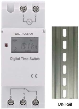
Figure 4.1: Timer with DIN rail. This image illustrates how the timer is designed to be mounted on a standard 35mm DIN rail.
4.1 Wiring Instructions
Refer to the wiring diagram below for proper connection. The timer operates on 24V AC/DC. The relay contacts are rated for up to 16A at 240V.

Figure 4.2: Wiring Example. This diagram shows how to connect the power input and load to the timer's terminals (1, 2 for power; 3, 4, 5 for relay output). It illustrates both normally open and normally closed connections for controlling loads.
- Terminals 1 & 2: Power input (24V AC/DC).
- Terminal 3: Common (COM) for the relay switch.
- Terminal 4: Normally Open (NO) contact. The circuit connected here will be ON when the timer is active (ON state).
- Terminal 5: Normally Closed (NC) contact. The circuit connected here will be OFF when the timer is active (ON state).
Note: The example wiring diagram shows a maximum load of 10 Amps or 1000 Watts for lighting. Always ensure your load does not exceed the timer's specified ratings (16A).
5. Initial Setup and Time Setting
Before programming, ensure the timer has power and the internal battery is charged (it has a 3-year power reserve). If the display is blank, connect power and allow it to charge for a few minutes.
5.1 Setting Current Time
- Press the CLOCK button (often labeled with a clock icon).
- While holding CLOCK, press the D+ button to set the current day of the week.
- While holding CLOCK, press the H+ button to set the current hour.
- While holding CLOCK, press the M+ button to set the current minute.
- Release the CLOCK button. The time is now set.
6. Programming ON/OFF Schedules
The timer supports up to 17 ON and 17 OFF programming events. Follow these steps to set your desired schedule:
- Press the P button. The display will show "1 ON". This indicates you are setting the first ON event.
- Press H+ to set the desired hour for the first ON event.
- Press M+ to set the desired minute for the first ON event.
- Press D+ to select the day(s) of the week for this ON event. You can cycle through options like "every day", "different day", "MO-FR", "MO-SA-SU", "MO WE FR", "TU TH SA", "MO-WE-TH-SA", etc. If the setting is for every day, you do not need to press this key.
- Press the P button again. The display will show "1 OFF". This indicates you are setting the first OFF event.
- Press H+ to set the desired hour for the first OFF event.
- Press M+ to set the desired minute for the first OFF event.
- If you want the same day setting as the ON event, you do not need to press the D+ key. Otherwise, press D+ to select the day(s) for this OFF event.
- Repeat steps 1-8 for additional ON/OFF programs (up to 17 pairs). The display will cycle through "2 ON", "2 OFF", and so on.
- To exit programming mode and save settings, press the CLOCK button. If you do not require all 17 settings, press the CLOCK button to end programming.
To clear a program: While in programming mode for a specific ON/OFF event, press the RESET button to clear that specific program step.
7. Operating Modes (Manual Override)
The timer typically operates in AUTO mode, following the programmed schedule. You can manually override the current state:
- Press the MANUAL button to cycle through operating modes:
- AUTO ON: The timer is currently ON and will follow the next programmed OFF event.
- AUTO OFF: The timer is currently OFF and will follow the next programmed ON event.
- ON: The timer is forced ON indefinitely, ignoring programmed events.
- OFF: The timer is forced OFF indefinitely, ignoring programmed events.
- To return to automatic operation, cycle through the modes until "AUTO ON" or "AUTO OFF" is displayed.
8. Maintenance
- Cleaning: Wipe the timer with a soft, dry cloth. Do not use abrasive cleaners or solvents.
- Battery: The internal lithium battery provides power reserve for up to 3 years. If the display becomes dim or loses time frequently, the battery may need replacement or recharging. The battery recharges when the timer is connected to power.
- Inspection: Periodically check wiring connections for tightness and signs of wear.
9. Troubleshooting
- Display is blank:
- Ensure the timer is connected to a 24V AC/DC power supply.
- Allow a few minutes for the internal battery to charge if it was fully depleted.
- Timer not switching ON/OFF as programmed:
- Verify the current time and day are set correctly.
- Check your programmed ON/OFF events for accuracy (time and day settings).
- Ensure the timer is in "AUTO ON" or "AUTO OFF" mode, not forced ON/OFF.
- Confirm wiring connections are secure and correct.
- Load not turning ON/OFF:
- Check the load itself (e.g., bulb is not burnt out).
- Verify the load's power requirements do not exceed the timer's 16A relay rating.
- Ensure the wiring to terminals 3, 4, and 5 is correct for your desired operation.
- Buttons are unresponsive:
- Try a full reset by pressing the RESET button (usually a small recessed button requiring a pointed object). Note: This will clear all programmed settings.
10. Specifications
| Model | 930247 |
| Operating Voltage | 24V AC/DC |
| Contact Rating | 16A @ 240V AC (SPDT) |
| Number of ON/OFF Programs | 17 ON & 17 OFF |
| Minimum Interval | 1 minute |
| Power Consumption | 7.5VA (MAX) |
| Display | LCD |
| Power Reserve | 3 years (lithium battery) |
| Ambient Temperature | -10°C to +40°C |
| Ambient Humidity | 35-85% RH |
| Mounting | 35mm DIN Rail |
| Dimensions (approx.) | 86mm (L) x 36mm (W) x 65mm (H) |
| Weight (approx.) | 150g (4.9 ounces) |
11. Warranty and Support
For warranty information or technical support, please refer to the documentation included with your purchase or contact Migro customer service. Keep your purchase receipt for warranty claims.
For further assistance, you may visit the Migro Store on Amazon.


