1. Introduction
This manual provides essential information for the safe and efficient operation of the SICK VS180-D430 Photoelectric Sensor. It covers installation, configuration, maintenance, and troubleshooting. Please read this manual thoroughly before operating the device to ensure proper function and to prevent damage or injury.
2. Safety Information
Always observe the following safety precautions:
- Disconnect power before installation, maintenance, or repair.
- Ensure proper grounding to prevent electrical shock.
- Do not expose the sensor to extreme temperatures, moisture, or corrosive substances beyond its specified operating conditions.
- Only qualified personnel should perform installation and wiring.
- Verify all connections are secure before applying power.
3. Product Overview
The SICK VS180-D430 is a compact photoelectric sensor designed for reliable object detection in industrial environments. It features a robust cylindrical housing and an M12 connector for easy integration.

Figure 3.1: Overview of the SICK VS180-D430 Photoelectric Sensor. This image shows the full cylindrical body of the sensor, including the threaded end for mounting and the M12 connector at the opposite end.

Figure 3.2: Close-up view of the SICK VS180-D430 sensor's identification label. The label clearly displays the model number "VS180-D430" and other manufacturing details.
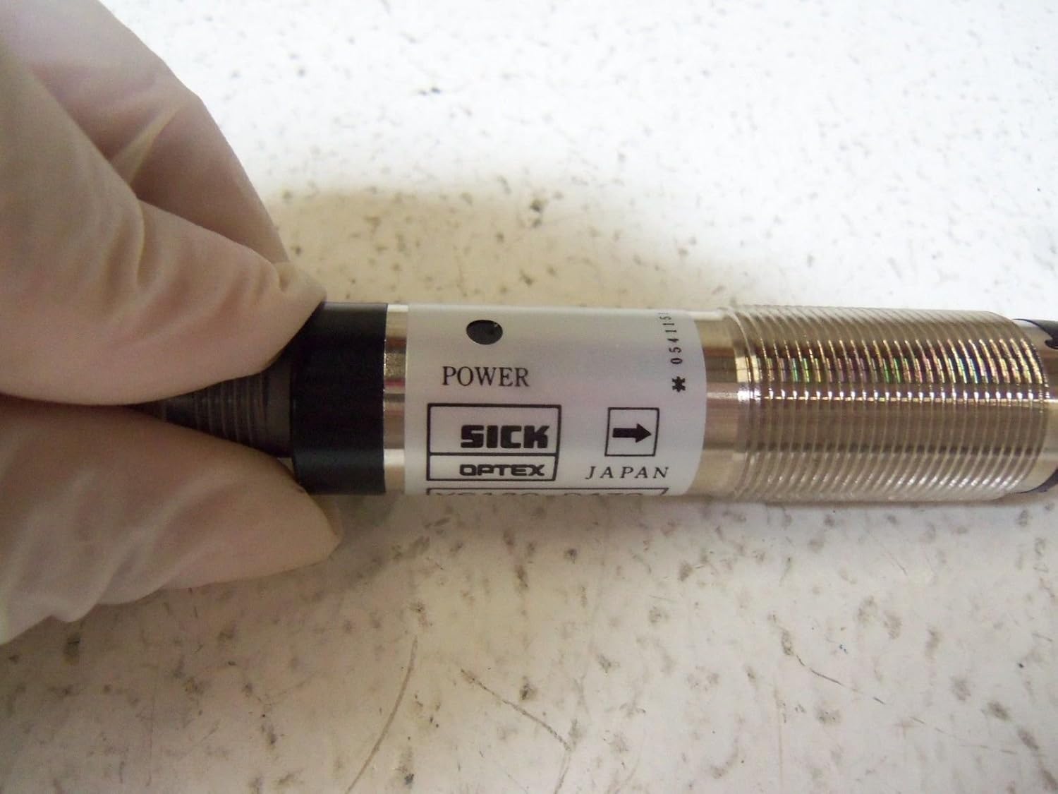
Figure 3.3: Detail of the SICK VS180-D430 sensor showing the 'POWER' indicator. This indicator illuminates when the sensor is receiving power, aiding in quick status checks.

Figure 3.4: View of the M12 connector end of the SICK VS180-D430 sensor. This threaded connector is standard for industrial applications, ensuring a secure and reliable electrical connection.
4. Setup and Installation
4.1 Mounting
The VS180-D430 sensor features a cylindrical M18 threaded housing for easy mounting. Secure the sensor using appropriate mounting brackets and nuts, ensuring it is firmly positioned to prevent vibration.
4.2 Wiring
The sensor uses a 4-pin M12 connector. Refer to the following pin assignment for correct wiring:
| Pin | Description | Wire Color (Standard) |
|---|---|---|
| 1 | L+ (12-24VDC) | Brown |
| 2 | Output (PNP/NPN) | White |
| 3 | M (0V / GND) | Blue |
| 4 | Output (PNP/NPN) | Black |
Ensure the power supply is within the specified 12-24VDC range.
5. Operating Instructions
Once installed and wired correctly, the VS180-D430 sensor operates automatically. The sensor emits a light beam and detects objects based on the reflection or interruption of this beam.
5.1 Indicator Lights
- Power Indicator: A green LED indicates that the sensor is powered on.
- Output Indicator: An orange or yellow LED indicates that the sensor has detected an object and the output is active.
5.2 Range Adjustment
Some models may feature a potentiometer for fine-tuning the detection range. If present, gently turn the potentiometer with a small screwdriver to adjust the sensitivity until reliable detection is achieved for your application.
6. Maintenance
The SICK VS180-D430 sensor is designed for low maintenance. However, regular checks can extend its lifespan and ensure optimal performance.
- Cleaning: Periodically clean the optical surfaces (lens) with a soft, lint-free cloth. Do not use abrasive cleaners or solvents.
- Connection Check: Ensure all electrical connections remain tight and free from corrosion.
- Mounting Stability: Verify that the sensor is still securely mounted and has not shifted due to vibration.
7. Troubleshooting
If the sensor is not functioning as expected, refer to the following common issues and solutions:
| Problem | Possible Cause | Solution |
|---|---|---|
| Sensor not powering on (no power LED) | No power supply; incorrect wiring; faulty cable. | Check power supply voltage (12-24VDC); verify wiring connections; test cable continuity. |
| Sensor not detecting objects | Dirty lens; misaligned sensor; object out of range; incorrect sensitivity setting. | Clean lens; realign sensor; ensure object is within specified range; adjust sensitivity if applicable. |
| Intermittent detection | Vibration; unstable mounting; electrical interference. | Secure mounting; check for sources of vibration; ensure proper shielding of cables. |
8. Specifications
Detailed technical specifications for the SICK VS180-D430 Photoelectric Sensor:
- Model: VS180-D430
- Sensor Type: Photoelectric Sensor
- Operating Voltage: 12-24 VDC
- Connection: 4-pin M12 Connector
- Detection Range: 0-25 meters (depending on specific variant and reflector)
- Housing Material: Typically nickel-plated brass or stainless steel
- Dimensions: Cylindrical, M18 thread (approx. 3.15 x 1.18 x 1.18 inches)
- Weight: Approximately 1.49 Pounds
- Manufacturer: SICK
- Date First Available: January 1, 2016
9. Warranty and Support
For warranty information and technical support, please contact SICK customer service or visit their official website. Keep your purchase receipt and product serial number handy for faster service.
SICK Official Website: www.sick.com


