1. Introduction
This manual provides essential information for the safe installation, operation, and maintenance of the Shihlin Magnetic Motor Starter, Model MSP100T. This device is designed for controlling 25 to 30HP, 3-phase electric motors operating on 208-240VAC systems, with a maximum current capacity of 100 amps. It features an adjustable overload relay with a range of 68 to 100 AMPS to protect the motor from overcurrent conditions.
Please read this manual thoroughly before installation and operation to ensure proper function and safety.
2. Safety Information
WARNING: Risk of Electric Shock and Injury.
- Installation and servicing must be performed by qualified electrical personnel only.
- Always disconnect power at the main circuit breaker before installing, servicing, or inspecting the motor starter.
- Ensure all wiring conforms to national and local electrical codes.
- This product contains chemicals known to the State of California to cause cancer and birth defects or other reproductive harm (Proposition 65 Warning). Handle with care and wash hands after contact.
- Do not operate the starter with the enclosure open or if any components are damaged.
- Proper grounding is essential for safe operation.
3. Product Overview
The Shihlin Magnetic Motor Starter (Model MSP100T) is a robust control device housed in a NEMA 1 metal enclosure. It integrates a contactor for switching motor power and an adjustable thermal overload relay for motor protection.

Figure 3.1: Magnetic Motor Starter with its NEMA 1 metal enclosure open, revealing the internal contactor and overload relay unit. The enclosure lid is shown beside the main unit.
Key Components:
- Contactor: The main switching device for the motor, rated for 100 amps.
- Adjustable Overload Relay: Provides thermal protection for the motor against sustained overcurrent. The amperage dial range is 60-100 AMPS.
- Auxiliary Contacts: Built-in Normally Open (NO) and Normally Closed (NC) contacts for control circuitry.
- Reset Button: Located on the overload relay, allows for manual or automatic reset after an overload trip.
- NEMA 1 Enclosure: A metal enclosure providing basic protection against dust and light indirect splashing. Includes four punch-outs for wire entry/exit and rubber grommets for wire protection.
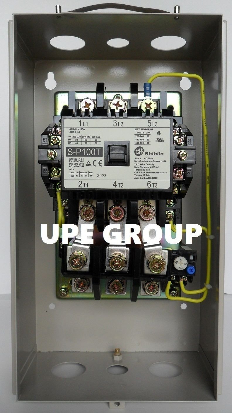
Figure 3.2: Detailed view of the internal contactor unit (S-P100T) with the overload relay attached below. Input terminals L1, L2, L3 and output terminals T1, T2, T3 are visible.

Figure 3.3: Close-up of the adjustable overload relay, showing the amperage dial (60-100 AMPS) and the blue reset button. The reset mechanism can be set to manual or auto.
4. Setup and Installation
4.1 Mounting
The motor starter should be mounted vertically on a flat, stable surface in a location that is easily accessible for wiring and maintenance, and protected from excessive moisture or dust. Use appropriate fasteners for the mounting holes provided on the enclosure.

Figure 4.1: Exterior view of the NEMA 1 metal enclosure for the motor starter. The front cover displays the "MOTOR STARTER P100T" label.
4.2 Wiring
A detailed wiring diagram is included with your motor starter. Refer to this diagram for specific connection points. Ensure all connections are tight and secure.
- Incoming Power: Connect the 3-phase 208-240VAC power supply to the L1, L2, L3 terminals of the contactor.
- Motor Connections: Connect the motor leads to the T1, T2, T3 terminals of the overload relay.
- Control Circuitry: Utilize the built-in auxiliary contacts (Normally Open & Normally Closed) for start/stop buttons, indicator lights, or other control logic as per your application's requirements.
- Grounding: Ensure the enclosure and motor are properly grounded according to electrical codes.
Use the provided rubber grommets in the enclosure punch-outs to protect wires from sharp edges.
4.3 Overload Relay Setting
The overload relay protects the motor from damage due to sustained overcurrent. Set the amperage dial on the overload relay to the motor's full load amperage (FLA) rating. The adjustable range is 60-100 AMPS. If the motor's FLA falls outside this range, a different overload relay may be required.
The reset button can be configured for manual or automatic reset. For most applications, manual reset is recommended for safety, requiring an operator to investigate the cause of the overload before restarting the motor.
5. Operating Instructions
5.1 Starting the Motor
Once installation and wiring are complete and verified, apply power to the motor starter. Press the "START" button (if wired) or activate the control circuit to energize the contactor. The motor should begin operation.
5.2 Stopping the Motor
Press the "STOP" button (if wired) or de-activate the control circuit to de-energize the contactor. The motor will stop.
5.3 Overload Trip and Reset
If the motor draws current exceeding the set point on the overload relay for a sustained period, the overload relay will trip, opening the control circuit and stopping the motor. This protects the motor from overheating.
- Manual Reset: After an overload trip, allow the motor and overload relay to cool down. Investigate and rectify the cause of the overload (e.g., mechanical binding, low voltage). Once the issue is resolved, press the blue reset button on the overload relay to reset it. The motor can then be restarted.
- Automatic Reset: If configured for auto-reset, the overload relay will automatically reset after cooling down. This is generally not recommended for safety reasons as the motor may restart unexpectedly.
6. Maintenance
Regular maintenance ensures reliable operation and extends the lifespan of the motor starter.
- Periodic Inspection: Annually inspect the starter for signs of wear, corrosion, or damage. Check for loose connections.
- Cleaning: Keep the enclosure clean and free of dust and debris. Ensure ventilation openings (if any) are not obstructed.
- Contact Inspection: Periodically inspect the contactor contacts for pitting or excessive wear. Replace the contactor if contacts are severely worn.
- Torque Check: Re-torque all electrical connections to specifications, especially after initial installation and during routine maintenance.
Always disconnect power before performing any maintenance.
7. Troubleshooting
- Motor Does Not Start:
- Check incoming power supply.
- Verify control circuit voltage and continuity.
- Ensure the overload relay is not tripped. If tripped, reset it after identifying and resolving the cause.
- Inspect contactor coil for proper operation.
- Check for loose wiring connections.
- Motor Trips on Overload:
- Verify the overload relay setting matches the motor's FLA.
- Check for mechanical binding or excessive load on the motor.
- Inspect motor for signs of damage or overheating.
- Check for unbalanced phases or low voltage conditions.
- Ensure proper ventilation for the motor and starter.
- Contactor Hums Loudly or Does Not Pull In Fully:
- Check control voltage. Low voltage can cause chattering or incomplete pull-in.
- Inspect contactor for foreign objects or mechanical obstruction.
- Contacts may be worn or pitted.
If troubleshooting steps do not resolve the issue, contact a qualified electrician or the manufacturer for assistance.
8. Specifications
| Feature | Specification |
|---|---|
| Product Model Number | MSP100T |
| Motor Horsepower (HP) | 25 - 30 HP |
| Voltage | 208 - 240 VAC |
| Amperage (Max) | 100 Amps |
| Phase | Three Phase / 3 Pole |
| Overload Relay Amperage Range | 60 - 100 Amps |
| Enclosure Type | NEMA 1 Metal Enclosure |
| Auxiliary Contacts | Built-in Normally Open & Normally Closed |
| Material | Steel |
| Item Weight | 15 Pounds |
| Product Dimensions (L x W x H) | 20 x 12 x 12 inches |
9. Warranty and Support
For warranty information, technical support, or additional wiring instructions, please contact the manufacturer, Shihlin, or your authorized distributor. Retain your purchase receipt for warranty claims.
Manufacturer: Shihlin

