Introduction
This manual provides comprehensive instructions for the installation, operation, and maintenance of the Intermatic EP100C 24-Hour 1 Circuit Electronic Control. This device is designed for precise control of electrical circuits, offering reliable scheduling for various applications.
Important Safety Information
CAUTION: RISK OF ELECTRICAL SHOCK. More than one disconnect switch may be required to de-energize the equipment before servicing. Use 10-18 gauge copper conductors rated for at least 75°C (167°F) for all connections.
PRECAUTION: RIESGO DE DESCARGA ELECTRICA. La instalación de varios interruptores de desconexión podría ser necesaria a fin de desactivar el equipo antes de llevar a cabo la reparación. Utilice conductores de cobre tamaño 10-18 conducidos con una especificación de al menos 75°C (167°F) para todas las conexiones.
Always disconnect power at the circuit breaker or fuse box before installing or servicing the control. Ensure all wiring is performed by a qualified electrician and complies with local and national electrical codes.
Setup and Installation
The Intermatic EP100C is designed for indoor/outdoor use and comes in a plastic enclosure. Follow these steps for proper installation:
1. Mounting
Securely mount the enclosure in a suitable location, ensuring it is protected from direct impact and excessive vibration. Use appropriate fasteners for the mounting surface.
2. Wiring
Before wiring, ensure all power to the circuit is disconnected. The unit features terminals for Timer Power, Line 1, and Load 1. Refer to the internal diagram for correct connections.
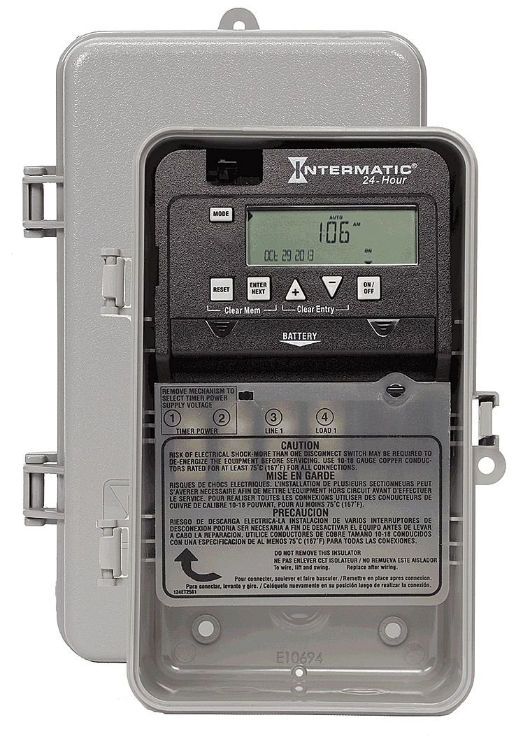
Figure 1: Internal View of Intermatic EP100C. This image shows the internal components of the EP100C electronic control, including the digital display, control buttons (MODE, RESET, ENTER NEXT, ON/OFF), and the wiring terminals labeled TIMER POWER, LINE 1, and LOAD 1. A battery compartment is also visible. Important safety warnings regarding electrical shock and conductor specifications are printed on the internal cover.
- Timer Power (1, 2): Connect the incoming power supply to these terminals.
- Line 1 (3): Connect the incoming hot wire for the controlled circuit.
- Load 1 (4): Connect the wire leading to the device being controlled.
DO NOT REMOVE THIS INSULATOR: To wire, lift and swing the insulator. Replace it after wiring to ensure proper insulation and safety.
3. Power Supply Voltage Selection
The unit supports 120-277 VAC. There is a mechanism inside to select the timer power supply voltage. Ensure this is set correctly for your application before applying power.
4. Battery Installation
Install the backup battery (type not specified, typically coin cell or AA/AAA) into the designated battery compartment. This battery maintains program settings during power outages.
Operating Instructions
The EP100C features a digital display and several control buttons for programming and manual operation.
1. Initial Setup and Time/Date Setting
- Press the MODE button to enter the setup menu.
- Use the ENTER NEXT button to navigate through time, date, and other settings.
- Use the + and - buttons (up/down arrows) to adjust values.
- Confirm each setting by pressing ENTER NEXT.
2. Programming ON/OFF Events
- Press MODE until you reach the program setting mode.
- Use ENTER NEXT to select a program slot (e.g., P1 ON, P1 OFF).
- Set the desired ON time using the + and - buttons.
- Press ENTER NEXT to save and move to the OFF time.
- Repeat for the OFF time.
- Continue for additional programs as needed.
3. Manual Override
Press the ON/OFF button to manually switch the controlled circuit ON or OFF, overriding the current program until the next scheduled event.
4. Resetting and Clearing Memory
- Press RESET to perform a full system reset, clearing all settings and programs.
- Press Clear Mem (Clear Memory) to erase programmed events without resetting the time/date.
- Press Clear Entry to clear the current input during programming.
Maintenance
Battery Replacement
The internal battery should be replaced periodically to ensure program retention during power outages. When the battery is low, an indicator may appear on the display. Disconnect power before replacing the battery.
Troubleshooting
| Problem | Possible Cause | Solution |
|---|---|---|
| Display is blank | No power to the unit; dead backup battery. | Check circuit breaker. Ensure wiring is correct. Replace backup battery. |
| Load does not turn ON/OFF as programmed | Incorrect program settings; manual override engaged; wiring issue. | Verify program times. Check if manual override is active. Inspect load wiring. |
| Unit resets unexpectedly | Power fluctuation; faulty battery. | Ensure stable power supply. Replace backup battery. |
Specifications
- Model: EP100C
- Type: 24-Hour 1 Circuit Electronic Control
- Voltage: 120-277 VAC
- Frequency: 60 Hz
- Switch Type: SPST (Single Pole Single Throw)
- Enclosure: Indoor/Outdoor Plastic Enclosure
- Dimensions: 9.5 x 5.75 x 3.75 inches
- Weight: 4 ounces
Support
For further assistance or technical support, please contact Intermatic customer service. Refer to the official Intermatic website for contact information and warranty details.


