1. Introduction
This manual provides essential information for the safe and efficient operation of the Balluff BIS00W2 RFID Read/Write Head. Please read this manual thoroughly before installation, operation, or maintenance to ensure proper use and to prevent damage to the device or injury to personnel. Keep this manual in a safe place for future reference.
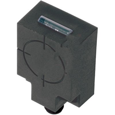
Figure 1: Balluff BIS00W2 RFID Read/Write Head. This image shows the compact, rectangular black housing of the RFID read/write head, featuring a translucent indicator light on the top surface and a circular target marking on its front face, indicating the optimal read/write area. A mounting point is visible at the bottom.
2. Safety Instructions
Observe all local and national safety regulations, as well as the specific instructions provided in this manual. Failure to comply with safety instructions may result in personal injury or equipment damage.
- Ensure power is disconnected before installation or maintenance.
- Only qualified personnel should install and service this device.
- Do not expose the device to extreme temperatures, moisture, or corrosive substances.
- Avoid strong electromagnetic fields near the device, as they may interfere with operation.
3. Setup and Installation
3.1 Unpacking
Carefully remove the BIS00W2 RFID Read/Write Head from its packaging. Inspect the device for any signs of damage during transit. Report any damage to the supplier immediately.
3.2 Mounting
- Select a suitable mounting location, ensuring sufficient clearance for cabling and optimal read/write performance.
- Mount the device securely using appropriate fasteners through the designated mounting holes.
- Ensure the read/write head is positioned correctly relative to the RFID tags for reliable detection.
3.3 Electrical Connection
The BIS00W2 features an RS-232 interface for communication. Connect the device to your control system according to the wiring diagram provided in the product datasheet (not included in this manual, refer to Balluff's official documentation). Ensure correct polarity and voltage supply.
- Power Supply: Refer to product specifications for required voltage.
- Data Interface: RS-232 serial communication.
4. Operating Instructions
4.1 Powering On
Once all electrical connections are secure, apply power to the device. The integrated LED indicator will illuminate to confirm power status and operational readiness.
4.2 Communication
The BIS00W2 communicates via RS-232. Configure your host system's serial port settings (baud rate, data bits, parity, stop bits) to match the device's specifications. Refer to the Balluff communication protocol documentation for detailed command structures and data formats.
4.3 Reading and Writing Tags
Position the RFID tag within the operational range of the read/write head. Use the appropriate commands via the RS-232 interface to initiate read or write operations. The LED indicator may change state to confirm successful tag interaction.
5. Maintenance
5.1 Cleaning
Keep the device clean and free from dust and debris. Use a soft, dry cloth for cleaning. Do not use abrasive cleaners or solvents, as they may damage the housing or indicator lens.
5.2 Inspection
Periodically inspect the device and its cabling for any signs of wear, damage, or loose connections. Address any issues promptly to ensure continued reliable operation.
5.3 Firmware Updates
Check the Balluff website for any available firmware updates for the BIS00W2. Follow the provided instructions carefully when performing updates.
6. Troubleshooting
| Problem | Possible Cause | Solution |
|---|---|---|
| Device not powering on | No power supply; incorrect wiring | Check power connections and voltage supply. Verify wiring against datasheet. |
| Cannot read RFID tags | Tag out of range; incorrect tag type; communication error | Ensure tag is within operational range. Verify tag compatibility. Check RS-232 communication settings. |
| Communication errors | Incorrect serial port settings; faulty cable | Verify baud rate, data bits, parity, and stop bits. Replace RS-232 cable if suspected faulty. |
If troubleshooting steps do not resolve the issue, contact Balluff technical support for further assistance.
7. Specifications
| Feature | Detail |
|---|---|
| Model Number | BIS00W2 |
| Type | RFID Read/Write Head |
| Dimensions | 50x40x24 mm (approximate, based on product title) |
| Frequency | HF (High Frequency) |
| Interface | RS-232 |
| Manufacturer | Balluff |
8. Warranty and Support
8.1 Warranty Information
Specific warranty terms and conditions for the Balluff BIS00W2 are provided at the time of purchase or can be found on the official Balluff website. Please retain your proof of purchase for warranty claims.
8.2 Technical Support
For technical assistance, product inquiries, or service requests, please contact Balluff customer support. Contact details can be found on the official Balluff website: www.balluff.com.


