1. Introduction
This manual provides instructions for the proper setup, operation, and maintenance of your Radical Professional Trinocular Polarizing Ore Reflected Light Microscope, Model ROM44IS300. This instrument is designed for advanced observations in fields such as geology, petrology, mineralogy, and pharmaceuticals, enabling both conoscopic and orthoscopic observations with incident light illumination and polarizing capabilities.
The microscope features a digital USB interface for live image and video recording, along with basic 2-dimensional measuring software for Windows 7 and later operating systems.
2. Safety Information
- Always handle the microscope with care to prevent damage to optical and mechanical components.
- Ensure the microscope is placed on a stable, level surface to prevent tipping.
- Disconnect the power cord before cleaning or performing any maintenance.
- Do not expose the microscope to direct sunlight, high temperatures, dust, or excessive humidity.
- Use only the provided power adapter.
- Avoid touching optical surfaces with bare hands. Use lens paper for cleaning.
3. Package Contents
Verify that all components are present and undamaged upon unpacking:
- Microscope Main Body with Reflected Light Illuminator
- Trinocular Head
- Eyepieces: WF 10x (2 units), 10x with Cross, 10x Micrometer
- Objectives: SEMI PLAN P4x, P10x, P40x (Spring Loaded)
- 3 Mega Pixel Camera with Optical Adapter
- USB Cable
- Power Adapter
- Compensators: Mica (1/4th Wavelength), Gypsum (Full Wavelength)
- Dust Cover
- User Manual (this document)
- Image/Video Software CD (or download link)
4. Component Identification
Familiarize yourself with the main parts of your microscope:

Figure 4.1: Overall view of the Radical Professional Trinocular Polarizing Ore Reflected Light Microscope. This image displays the main body, trinocular head, objectives, stage, and the mounted 3-megapixel camera on top.
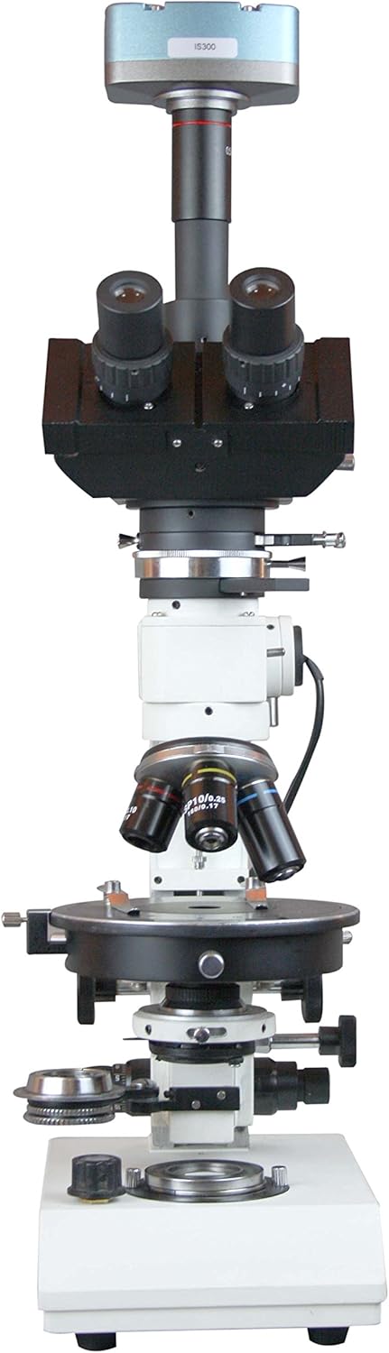
Figure 4.2: Front view of the microscope, highlighting the objective turret, mechanical stage, and focusing knobs. The reflected light illuminator is visible on the side.

Figure 4.3: Side view of the microscope, showing the coarse and fine focus knobs, the stage controls, and the power switch for the illuminator. The trinocular head is angled at 45 degrees.

Figure 4.4: Top-down view of the microscope, emphasizing the trinocular head with eyepieces and the mounted digital camera. The objective lenses are also visible from this angle.
- Trinocular Head: Inclined at 45 degrees, rotatable 360 degrees, with slots for retarding plates and a sliding Bertrand lens.
- Eyepieces: WF 10x, 10x with Cross, and 10x Micrometer.
- Objectives: SEMI PLAN P4x, P10x, P40x (spring-loaded for protection).
- Reflected Light Illuminator: Provides incident light for opaque samples.
- Polarizer: Swing-out design for incident light.
- Analyzer: 360-degree rotation, swing-out for brightfield observation.
- Compensator Slots: For Mica (1/4th Wavelength) and Gypsum (Full Wavelength) compensators.
- Mechanical Stage: For precise sample positioning.
- Coarse and Fine Focus Knobs: For adjusting sample focus.
- 3Mpix Camera: Digital camera for image and video capture, mounted on the trinocular port.
5. Setup
5.1 Unpacking and Placement
- Carefully remove all components from the packaging.
- Place the microscope base on a stable, vibration-free surface.
- Retain all packaging materials for future transport or storage.
5.2 Assembly
- Install Trinocular Head: Gently place the trinocular head onto the top of the microscope body. Secure it with the set screw.
- Insert Eyepieces: Insert the WF 10x eyepieces into the binocular tubes. Insert the 10x with Cross and 10x Micrometer eyepieces as needed for specific observations.
- Attach Objectives: Screw the SEMI PLAN P4x, P10x, and P40x objectives into the revolving nosepiece in increasing order of magnification.
- Mount Digital Camera: Attach the 3Mpix camera to the trinocular port using the optical adapter. Connect the camera to your computer via the provided USB cable.
- Connect Power: Plug the power adapter into the microscope's power input and then into a suitable electrical outlet.
6. Operating Instructions
6.1 Powering On and Illumination
- Ensure the power cord is securely connected.
- Flip the power switch (usually located on the base or side) to the "ON" position.
- Adjust the brightness control knob for the reflected light illuminator to a comfortable level.
6.2 Sample Placement and Focusing
- Place your sample (e.g., polished ore section) on the mechanical stage.
- Secure the sample using the stage clips.
- Rotate the nosepiece to select the lowest power objective (P4x).
- Using the stage control knobs, position the sample so the area of interest is under the objective.
- Look through the eyepieces and use the coarse focus knob to bring the sample into approximate focus.
- Use the fine focus knob for precise focusing.
- Adjust interpupillary distance and diopter settings on the eyepieces for comfortable viewing.
- Switch to higher power objectives (P10x, P40x) as needed, making minor adjustments with the fine focus knob.
6.3 Polarizing Observations
- Engage Polarizer: Swing the polarizer into the light path of the reflected illuminator.
- Engage Analyzer: Rotate the analyzer into the light path. For crossed polars, rotate the analyzer until the field of view is dark.
- Insert Compensators: For specific optical properties, insert the Mica (1/4th Wavelength) or Gypsum (Full Wavelength) compensator into the designated slots in the trinocular head.
- Bertrand Lens: For conoscopic observations (interference figures), engage the sliding Bertrand lens.
6.4 Digital Imaging with 3Mpix Camera
- Ensure the 3Mpix camera is connected to your computer via USB.
- Install the provided image/video software on your Windows 7 (or later) computer.
- Launch the software. The live view from the microscope camera should appear on your screen.
- Adjust camera settings (exposure, white balance) within the software for optimal image quality.
- Use the software to capture still images or record videos.
- Utilize the basic 2-dimensional measuring functions as required.
7. Maintenance
7.1 Cleaning
- Optical Components: Use a soft brush or air blower to remove dust. For smudges, use lens paper lightly moistened with lens cleaning solution. Wipe gently in one direction.
- Microscope Body: Wipe external surfaces with a soft, damp cloth. Avoid using harsh chemicals or solvents.
7.2 Storage
- When not in use, cover the microscope with the provided dust cover to protect it from dust and debris.
- Store in a cool, dry place, away from direct sunlight and extreme temperatures.
8. Troubleshooting
| Problem | Possible Cause | Solution |
|---|---|---|
| No illumination | Power cord disconnected; power switch off; bulb failure | Check power connection; turn on switch; replace bulb (if applicable, consult service) |
| Image blurry/cannot focus | Objective not fully engaged; coarse/fine focus not adjusted; sample upside down | Rotate nosepiece until objective clicks into place; adjust focus knobs; reorient sample |
| Dark field with crossed polars is not completely dark | Analyzer not fully rotated; polarizer not correctly aligned | Rotate analyzer to achieve extinction; ensure polarizer is correctly positioned in the light path |
| Camera not detected by computer | USB cable loose; software not installed; driver issue | Check USB connection; install software/drivers; try a different USB port |
9. Specifications
| Feature | Specification |
|---|---|
| Model Number | ROM44IS300 |
| Head | Trinocular, Inclined at 45 Degrees, Rotatable 360 degrees, with slots for Retarding plates & Sliding Bertrand Lens |
| Eyepieces | WF 10x, 10x with Cross, 10x Micrometer |
| Objectives | SEMI PLAN P4x, P10x, P40x (Spring Loaded) |
| Polarizer | Swing Out Polarizer |
| Analyzer | 360 Degrees Rotation, Swing-out for bright field |
| Compensators | Mica: 1/4th Wavelength, Gypsum: Full Wavelength |
| Camera | Professional Metal casing 3 Mega Pixel Camera with Optical Adapter |
| Software | Image/Video Software with Basic 2 Dimensional Measuring for WINDOWS WIN 7 (and later) |
| Light Source Type | Halogen |
| Material | Metal |
| Real Angle of View | 45 Degrees |
| Maximum Magnification | 600 x |
| Power Source | Adapter |
| Parcel Dimensions | 53.34 x 45.72 x 25.4 cm |
| Item Weight | 11.57 kg |
10. Warranty and Support
For warranty information and technical support, please refer to the documentation provided with your purchase or contact Radical customer service directly. Keep your purchase receipt as proof of purchase.
For further assistance, visit the official Radical website or contact your local distributor.


