Introduction
This manual provides detailed instructions for the installation, operation, and maintenance of your Inkbird ITC-100VH Digital PID Temperature Controller. Please read this manual thoroughly before use to ensure proper function and safety.
Safety Information
- Ensure all wiring is performed by a qualified professional and adheres to local electrical codes.
- Disconnect power before performing any wiring or maintenance.
- Do not operate the device in environments with excessive moisture, dust, or corrosive gases.
- The device operates on AC 100-240V. Verify your power supply matches this requirement.
- The heat sink must be properly installed to dissipate heat from the Solid State Relay (SSR).
Package Contents
The standard package includes:
- 1 x Inkbird ITC-100VH PID Temperature Controller
- 1 x 25A Solid State Relay (SSR-25 DA)
- 1 x K-Type Thermocouple
- 1 x White Heat Sink

Image: The complete kit including the PID controller, solid state relay, K-type thermocouple, and heat sink.
Product Overview
Front Panel

Image: Front view of the ITC-100VH controller, showing the digital display for Process Value (PV) and Set Value (SV), output indicators (OUT, AL1, AL2, RUN), and control buttons (ITC, SET, AT/RUN, Up, Down).
- PV (Process Value): Displays the current measured temperature. (Red LED)
- SV (Set Value): Displays the target temperature or parameter setting. (Green LED)
- OUT Indicator: Illuminates when the control output is active.
- AL1/AL2 Indicators: Illuminates when alarm 1 or alarm 2 is active.
- RUN Indicator: Illuminates when the controller is in operation.
- ITC Button: Used to enter parameter setting mode.
- SET Button: Used to confirm settings or cycle through parameters.
- AT/RUN Button: Used to initiate auto-tuning or start/stop operation.
- Up/Down Arrows: Used to adjust values.
Rear Terminals
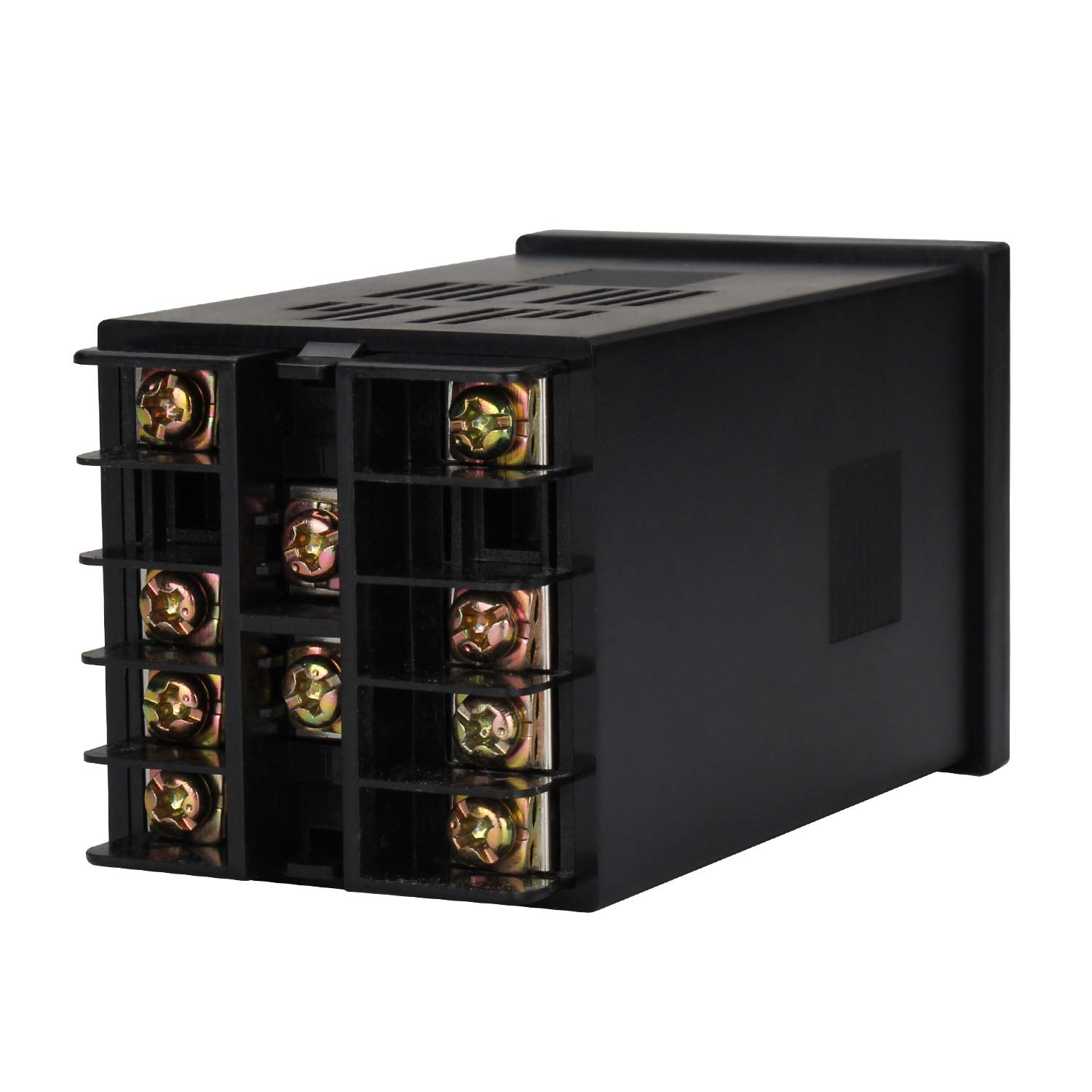
Image: Rear view of the ITC-100VH controller, showing the screw terminals for power input, sensor input, and control outputs.
Solid State Relay (SSR)
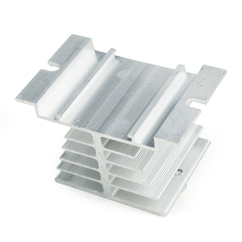
Image: Close-up of the Inkbird SSR-25 DA Solid State Relay, showing input (3-32VDC) and load (24-380VAC) terminals.
K-Type Thermocouple
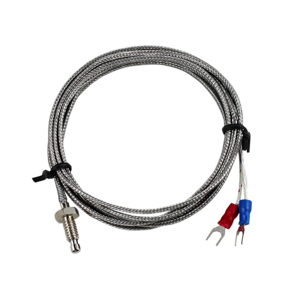
Image: K-Type Thermocouple with a metal probe, braided cable, and red/blue spade connectors for wiring.
Heat Sink

Image: Aluminum heat sink with fins, designed to dissipate heat from the Solid State Relay.
Specifications
| Feature | Specification |
|---|---|
| Power Supply Voltage | AC 100-240V, 50/60Hz |
| Operating Voltage Range | 85-110% Rated voltage |
| Power Consumption | Approx. 5VA |
| Display Accuracy | ±0.2%FS 0.1°C (<1000°C); 1°C (≥1000°C) |
| Sampling Period | 0.5 seconds |
| Temperature Compensation | 0-50°C |
| Output | 1 x SSR output (DC 12V, 30mA), 1 x Relay Alarm Output (AC250V 3A) |
| Environmental Conditions | -10 to 55°C, 35-85% RH (non-condensing) |
| Storage Temperature | -25 to 65°C (non-condensing) |
| Data Storage | 10 years |
| Cutout Size | 45mm x 45mm |
| K-Type Thermocouple Range | 0-400°C |
| K-Type Thermocouple Cable Length | 2m (6.6ft) |
| SSR Load Voltage | 24-380VAC |
| SSR Load Current | 25A |
| SSR Input Voltage | DC 3-32V |
| Heat Sink Dimensions | Roof: 50x60mm, Foot: 80x50mm, Height: 50mm |
Setup and Installation
Mounting the Controller
The ITC-100VH controller is designed for flush mounting.
- Cut a square opening of 45mm x 45mm in your panel.
- Insert the controller into the opening.
- Secure the controller using the provided mounting brackets from the rear.

Image: A white plastic mounting bracket used to secure the PID controller into a panel cutout.
Wiring Diagram
Refer to the wiring diagram below for proper connections. Ensure all connections are secure and correct before applying power. Incorrect wiring can damage the device or cause safety hazards.

Image: Detailed wiring diagram showing connections for power supply, K-type thermocouple, and the solid state relay (SSR) to the ITC-100VH controller.
- Power Input (Terminals 1 & 2): Connect AC 100-240V power supply.
- Thermocouple Input (Terminals 9 & 10): Connect the K-type thermocouple. Ensure correct polarity (red to positive, blue to negative if applicable, or follow markings on the thermocouple).
- SSR Output (Terminals 4 & 5): Connect the DC 12V output from the controller to the input terminals (3-32VDC) of the Solid State Relay.
- Alarm Output (Terminals 6 & 7): Connect external alarm device if required.
- SSR Load Connections: Connect your heating element or load to the load terminals (24-380VAC) of the SSR.
Heat Sink Installation
The heat sink is essential for the proper operation and longevity of the Solid State Relay.
- Apply a thin layer of thermal paste (not included) between the SSR and the heat sink for optimal heat transfer.
- Mount the SSR securely to the heat sink using screws.
- Ensure adequate airflow around the heat sink to prevent overheating.
Operating Instructions
Initial Power-Up
After completing all wiring, apply power to the controller. The PV display will show the current temperature, and the SV display will show the default set temperature.
Setting the Target Temperature (SV)
- Press the SET button once. The SV display will flash.
- Use the Up and Down arrow buttons to adjust the target temperature.
- Press the SET button again to confirm the new value and exit the setting mode.
Parameter Settings
To access advanced parameters:
- Press and hold the SET button for approximately 3 seconds until the first parameter code appears on the PV display.
- Use the Up and Down arrow buttons to navigate through the parameter codes.
- Press SET to view the value of the selected parameter.
- Use the Up and Down arrow buttons to change the parameter value.
- Press SET to confirm the new value.
- To exit parameter setting mode, press and hold the SET button for 3 seconds, or wait for 30 seconds of inactivity.
Refer to the detailed parameter list in the full user manual for specific parameter codes and their functions (e.g., P, I, D values, alarm types, input sensor type).
Auto-Tuning Function
The auto-tuning function helps the controller optimize its PID parameters for your specific heating system, improving temperature stability and accuracy.
- Set your desired target temperature (SV).
- Press and hold the AT/RUN button for approximately 3 seconds. The AT indicator will flash, indicating auto-tuning is in progress.
- The controller will cycle the output to determine the optimal PID values. This process may take some time, depending on your system's thermal characteristics.
- Once auto-tuning is complete, the AT indicator will stop flashing, and the controller will operate with the newly calculated PID parameters.
Note: During auto-tuning, the temperature may overshoot or undershoot the set value. This is normal behavior.
Maintenance
- Keep the controller clean and free from dust. Use a soft, dry cloth for cleaning.
- Regularly inspect wiring connections for tightness and signs of wear or corrosion.
- Ensure the heat sink for the SSR is free from obstructions and has adequate ventilation.
- Avoid exposing the device to direct sunlight, high temperatures, or excessive humidity.
Troubleshooting
- Display shows "HHHH" or "LLLL"
- This indicates a sensor error. Check the K-type thermocouple connection for proper polarity and ensure it is not damaged or open-circuited.
- Temperature reading is inaccurate
- Verify the thermocouple is correctly installed and making good contact with the measurement point. Check for electromagnetic interference. Consider performing auto-tuning.
- Controller not heating/cooling
- Check power supply to the controller and the load. Verify SSR wiring and functionality. Ensure the set temperature (SV) is correctly configured relative to the current temperature (PV) and control mode.
- Temperature fluctuates widely
- This may indicate incorrect PID parameters. Perform the auto-tuning function. Ensure the heating element and sensor are appropriately sized for the application.
Warranty and Support
Inkbird products typically come with a standard manufacturer's warranty. For specific warranty terms, technical support, or service inquiries, please refer to the official Inkbird website or contact their customer service directly. Keep your purchase receipt for warranty claims.