1. Introduction
This manual provides essential instructions for the installation, operation, and maintenance of the Cisco DS-C9124-K9 MDS 9124 24-Port Fabric Switch. Please read this manual thoroughly before using the device to ensure proper functionality and safety.
2. Safety Information
Important Safety Instructions:
- Ensure proper grounding for the device.
- Do not operate the switch in wet or humid conditions.
- Disconnect power before performing any maintenance or installation procedures.
- This unit is suitable for an IT power system connection of max 230 V Phase-Phase.
- Observe all warning labels on the device.

Image Description: A close-up of a warning label on the switch, indicating "Class 1 Laser" and stating that "This unit is suitable for an IT power system connection of max 230 V Phase-Phase."
3. Product Overview
The Cisco DS-C9124-K9 MDS 9124 is a 24-port Multilayer Fabric Switch designed for high-performance storage area networks (SANs).
3.1 Front Panel
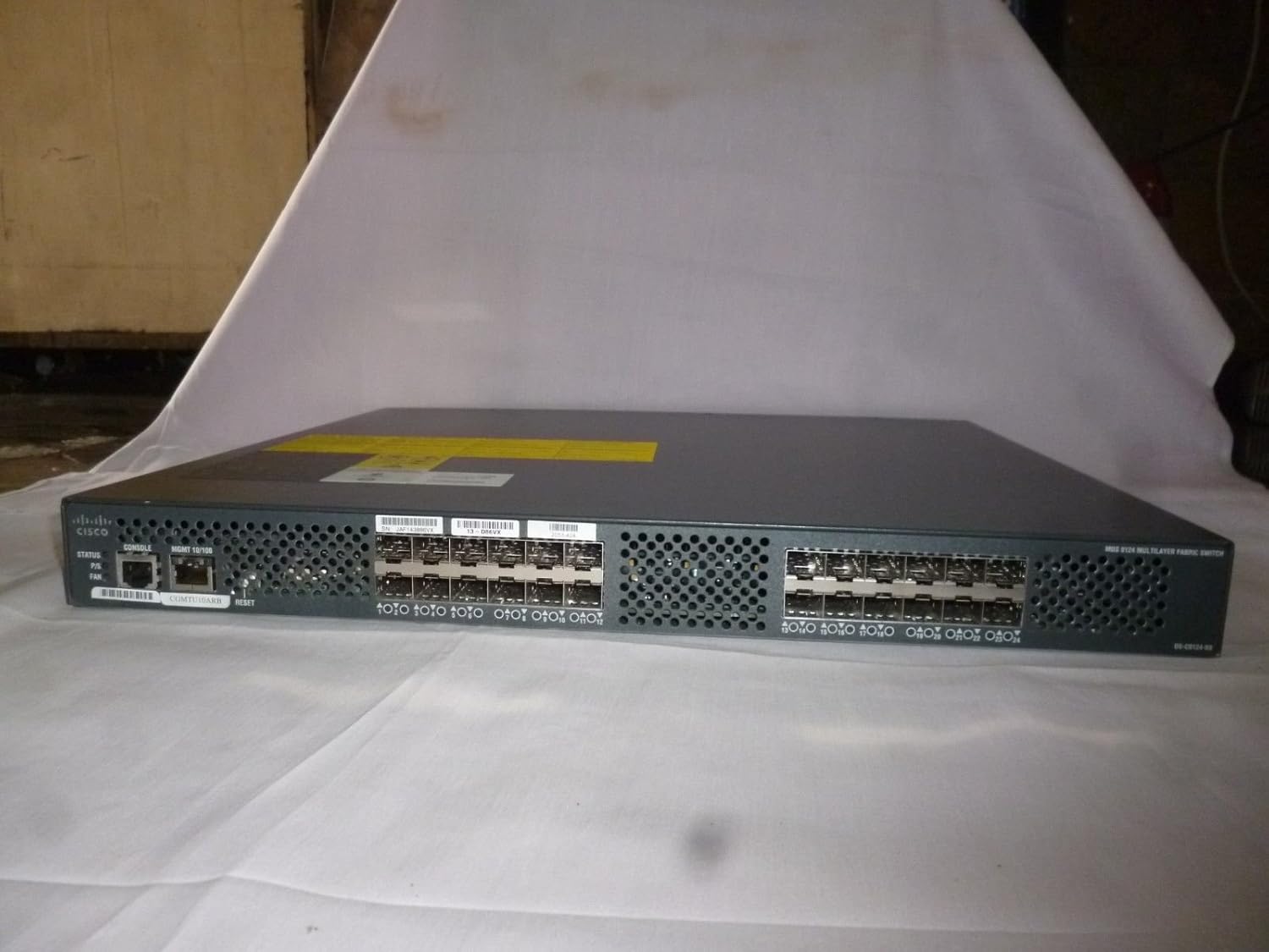
Image Description: A full front view of the Cisco DS-C9124-K9 switch, showing the 24 SFP ports, console port, management port, status LEDs, and reset button on the left side. The right side shows the 24 SFP ports.
- 24 SFP Ports: For fiber channel connectivity.
- Console Port: RJ-45 serial console for local management.
- MGMT 10/100 Port: RJ-45 Ethernet port for out-of-band management.
- Status LEDs: Indicators for power, system status, and fan operation.
- Reset Button: For restarting the device.

Image Description: A close-up of the left side of the switch's front panel, highlighting the CONSOLE port, MGMT 10/100 port, STATUS, P/S (Power Supply), and FAN LEDs, along with the RESET button.

Image Description: A close-up view of the 24 SFP (Small Form-Factor Pluggable) ports on the front panel of the switch, labeled 1 through 24.

Image Description: A detailed view of the first 12 SFP ports (1-12) on the front panel of the Cisco switch, showing the empty slots for transceivers.
3.2 Rear Panel

Image Description: A full rear view of the Cisco DS-C9124-K9 switch, displaying the power input module with an AC inlet and power switch, along with multiple fan exhaust vents.
- Power Input: AC power connector with an on/off switch.
- Fan Modules: Integrated cooling fans for heat dissipation.

Image Description: A close-up of the power input module on the rear panel, showing the AC power inlet, the power switch, and the "DS-C24-300AC" label, along with input/output OK LEDs.
4. Setup and Installation
Follow these steps to properly install your Cisco DS-C9124-K9 switch.
- Unpacking: Carefully remove the switch from its packaging. Inspect for any physical damage.
- Mounting: The switch can be rack-mounted. Secure it using appropriate rack-mounting hardware (not included). Ensure adequate airflow around the unit.
- Power Connection:
- Connect the provided AC power cord to the power input on the rear panel.
- Plug the other end of the power cord into a grounded electrical outlet.
- Ensure the power switch on the rear panel is in the OFF position before connecting.
- Network Connections:
- Insert SFP transceivers into the desired fiber channel ports on the front panel.
- Connect fiber optic cables from your SAN devices to the SFP transceivers.
- For management, connect an Ethernet cable from your management workstation to the MGMT 10/100 port.
- For console access, connect a serial cable from your workstation to the CONSOLE port.
- Power On: Flip the power switch on the rear panel to the ON position. Observe the STATUS LEDs on the front panel.
5. Operating Instructions
Once the switch is powered on and connected, you can begin configuration and operation.
- Initial Configuration: Access the switch via the console port or the management Ethernet port using a terminal emulator (e.g., PuTTY) and the appropriate IP address. Refer to Cisco documentation for detailed command-line interface (CLI) configuration.
- Monitoring Status: The front panel LEDs provide a quick visual status:
- STATUS: Indicates overall system health.
- P/S: Indicates power supply status.
- FAN: Indicates fan operation status.
- Port Activity: Each SFP port typically has an LED to indicate link status and activity.
6. Maintenance
Regular maintenance ensures optimal performance and longevity of your switch.
- Cleaning: Periodically clean the exterior of the switch with a soft, dry cloth. Ensure ventilation openings are free from dust and debris. Do not use liquid cleaners.
- Firmware Updates: Regularly check the Cisco support website for the latest firmware updates. Follow Cisco's instructions for firmware upgrade procedures.
- Environmental Control: Maintain the operating environment within specified temperature and humidity ranges to prevent overheating and component damage.
7. Troubleshooting
This section provides solutions to common issues you might encounter.
| Problem | Possible Cause | Solution |
|---|---|---|
| Switch does not power on. | No power, faulty power cord, power switch off. | Check power cord connection, ensure power outlet is active, verify power switch is ON. |
| No link light on SFP port. | Faulty SFP transceiver, incorrect fiber cable, remote device off. | Verify SFP transceiver is properly seated, check fiber cable integrity, ensure connected device is powered on and configured. |
| Cannot access management interface. | Incorrect IP address, network cable issue, firewall. | Verify IP configuration, check Ethernet cable, temporarily disable local firewall for testing. Try console access. |
8. Specifications
Technical specifications for the Cisco DS-C9124-K9 MDS 9124 24-Port Fabric Switch.
- Model: DS-C9124-K9
- Ports: 24 x SFP Fiber Channel ports
- Management Ports: 1 x Console (RJ-45), 1 x MGMT 10/100 (RJ-45)
- Power Input: 100-240 VAC, 4-2 A, 50-60 Hz (as seen on power supply label DS-C24-300AC)
- Manufacturer: CISCO SYSTEMS - ENTERPRISE
- ASIN: B011YZLTO0
- Date First Available: July 18, 2015
- Serial Number Example: JAF143886VX
- Part Number Example: 68-2714-06 D0
- Product ID Example: DS-C9124-K9 V04

Image Description: A close-up of a product label on the switch, displaying manufacturing date (2010-09), "MADE IN CHINA", a barcode, part number "68-2714-06 D0", and product ID "DS-C9124-K9 V04".
9. Warranty and Support
For warranty information and technical support, please refer to the official Cisco website or contact Cisco customer service directly. Keep your purchase receipt and product serial number (e.g., JAF143886VX) readily available when seeking support.
Image Description: A close-up of a product label on the switch, showing a serial number (SN: JAF143886VX) and other identification codes.


