1. Introduction
The Viking Electronics RC-4A is a network-enabled relay controller designed to provide remote control and monitoring capabilities for various applications. It allows for networked control of four relays and monitoring of four contact closure inputs through an intuitive web interface. This manual provides detailed instructions for the proper installation, configuration, and operation of your RC-4A controller.
Key Features:
- Networked control of four relays via an easy-to-use web interface.
- Monitoring of four contact closure inputs.
- Relays can be toggled on/off or activated for a specified duration (1 to 99 seconds).
- Configurable as a secure remote relay for Viking VoIP series phones, ideal for door strikes and gate control.
- Ability to send email or text message notifications in response to sensor input changes.
- Remote interaction feature: sensor activity on one RC-4A can trigger a relay on a second RC-4A across the network.
- Ready-to-use webpage control interface with encrypted login.
- Two levels of user access: Administrator (full access) and Guest (programmable limits).
- Customizable relay names, input names, and input status on the webpage.
- Firmware updatable.
2. Safety Information
Please read and understand all safety instructions before installing or operating the RC-4A controller. Failure to follow these instructions may result in electric shock, fire, or damage to the device. Always disconnect power before performing any wiring or maintenance. Ensure all connections are secure and comply with local electrical codes. This device is intended for indoor use only in a dry environment.
3. Package Contents
Verify that all items are present in the package:
- RC-4A Network Enabled 4 Relay Controller
- (Additional items, if any, would be listed here. Based on "Whats in the box: Controller", only the controller is explicitly mentioned.)
4. Product Overview
The RC-4A controller features terminal strip connections for its four relays and four sensor inputs. It is designed for easy integration into existing network infrastructures, providing remote control and monitoring capabilities.
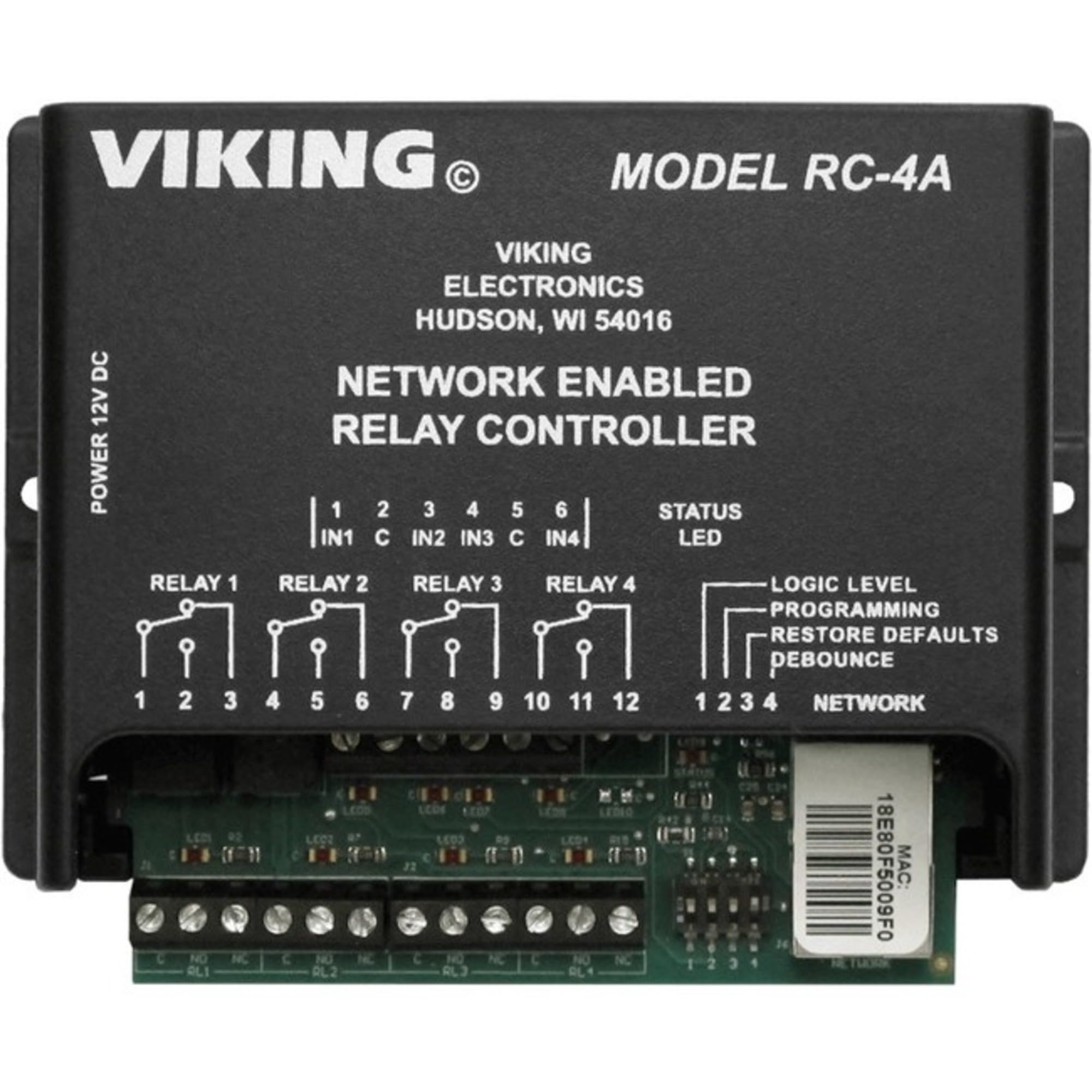
Figure 1: Front view of the RC-4A Network Enabled 4 Relay Controller, showing terminal strip connections for relays and sensor inputs.
Components:
- Relay Terminal Strips: Four sets of connections (Normally Open, Normally Closed, Common) for controlling external devices.
- Sensor Input Terminal Strips: Four sets of connections for monitoring contact closure inputs.
- Network Port: RJ45 port for Ethernet connection to your local network.
- Power Input: Connection for the power supply (not explicitly mentioned in product details, but implied for operation).
- Status Indicators: LEDs (assumed) to show power, network activity, and relay/sensor status.
5. Setup
5.1. Mounting
The RC-4A supports DIN Rail Mount. Secure the controller in a suitable location, ensuring adequate ventilation and access to wiring terminals.
5.2. Wiring Connections
- Power Connection: Connect the appropriate power supply to the RC-4A's power input. Ensure the power source matches the device's requirements (voltage/current).
- Network Connection: Connect an Ethernet cable from your network switch or router to the RC-4A's network port. The device will obtain an IP address via DHCP by default.
- Relay Connections: For each of the four relays, connect your external devices (e.g., door strikes, gates, lights) to the Normally Open (NO), Normally Closed (NC), and Common (C) terminals as required by your application. The relays are rated for 4 Amps.
- Sensor Input Connections: Connect your contact closure sensors (e.g., door sensors, push buttons) to the four sensor input terminal strips.
5.3. Initial Network Access
Once powered and connected to the network, the RC-4A will acquire an IP address. You can typically discover its IP address using network scanning tools or by checking your router's DHCP client list. Access the web interface by entering the RC-4A's IP address into a web browser.
The default login credentials will be required for initial access. Refer to the device's label or accompanying documentation for default username and password. It is highly recommended to change these default credentials immediately after the first login for security purposes.
6. Operating Instructions
The RC-4A is operated primarily through its web-based interface, which provides comprehensive control and monitoring capabilities.
6.1. Web Interface Overview
After logging in, the web interface will display the status of all four relays and four sensor inputs. You can customize the names of relays and inputs for easier identification.
6.2. Controlling Relays
- Toggle On/Off: From the web interface, you can manually switch each relay between its Normally Open and Normally Closed states.
- Timed Closures: Relays can be activated for a specific duration, ranging from 1 to 99 seconds. This is useful for momentary actions like unlocking a door.
6.3. Monitoring Sensor Inputs
The web interface displays the current status of each of the four contact closure inputs. This allows for real-time monitoring of connected sensors.
6.4. Email and Text Notifications
Configure the RC-4A to send email or text message notifications when a change in state is detected on one or more sensor inputs. This feature requires proper SMTP server settings to be configured within the web interface.
6.5. Remote Interaction (RC-4A to RC-4A)
Two RC-4A units can be configured to interact over the network. A change in a sensor input on one RC-4A can be programmed to trigger a specific relay on a second RC-4A. This enables distributed control and automation.
6.6. User Access Levels
The RC-4A supports two levels of user access:
- Administrator: Has full access to all operational and programming settings, including network configuration, user management, and relay/sensor settings.
- Guest: Has limited operational control, with programmable restrictions set by the Administrator. Guests cannot modify programming or critical settings.
7. Maintenance
- Firmware Updates: Periodically check the manufacturer's website for firmware updates. Firmware can be updated via the web interface to ensure optimal performance and access to new features.
- Cleaning: Keep the device clean and free from dust. Use a dry, soft cloth for cleaning. Do not use liquid cleaners or solvents.
- Environmental Conditions: Ensure the operating environment remains within the specified temperature and humidity ranges to prevent damage.
8. Troubleshooting
- Device Not Powering On:
Ensure the power supply is correctly connected and providing the correct voltage. Check the power outlet.
- Cannot Access Web Interface:
Verify the Ethernet cable is securely connected. Check network connectivity and ensure the RC-4A has obtained an IP address. Confirm you are using the correct IP address and port (if applicable). Temporarily disable any firewall on your computer.
- Relays Not Activating:
Check wiring connections to the external device. Ensure the relay is being commanded correctly from the web interface. Verify the external device is functioning independently.
- Sensor Inputs Not Responding:
Check the wiring of the sensor to the input terminals. Ensure the sensor is functioning correctly and providing a valid contact closure signal.
- Email/Text Notifications Not Sending:
Verify SMTP server settings, recipient addresses, and network access for outgoing mail. Check spam folders for notifications.
9. Specifications
| Model Number | VK-RC-4A |
| Brand | VIKING |
| Connector Type | Screw |
| Contact Material | Copper |
| Contact Type | 2NO 2NC (for each relay, implying Normally Open and Normally Closed contacts) |
| Current Rating (Relay) | 4 Amps |
| Mounting Type | DIN Rail Mount |
| Operation Mode | Automatic |
| Smart Home Compatibility | Smart Home Compatible |
| Product Dimensions | 8 x 8 x 5 inches |
| Item Weight | 1.5 pounds |
| UPC | 615687226522 |
| Manufacturer | Viking Components |
10. Warranty and Support
For warranty information and technical support, please refer to the official Viking Electronics website or contact their customer service department. Keep your purchase receipt as proof of purchase for warranty claims.
Viking Electronics Official Website: www.vikingelectronics.com
For further assistance, consult the detailed documentation available on the manufacturer's website or contact their technical support team directly.


