1. Introduction
This manual provides detailed instructions for the proper installation, operation, and maintenance of the Balluff BCC M323-M313-30-300-PX0334-003 Micro Cordset. This cordset is a 3-pole, double-ended cable designed for industrial applications, featuring a male straight connector on one end and a female 90-degree connector on the other.
Please read this manual thoroughly before using the product to ensure safe and efficient operation.
2. Safety Information
WARNING: Electrical Hazard
- Always disconnect power before installing, servicing, or removing the cordset.
- Ensure all connections are secure and properly seated to prevent electrical shorts or intermittent operation.
- Do not use the cordset if it appears damaged, frayed, or has exposed wiring.
- This product is designed for specific industrial applications. Do not use it for purposes other than its intended use.
- Installation should be performed by qualified personnel in accordance with all local and national electrical codes.
3. Product Overview
The Balluff BCC M323-M313-30-300-PX0334-003 is a robust micro cordset designed for reliable signal transmission in industrial environments. It features a durable cable and high-quality connectors.

Figure 3.1: Balluff BCC M323-M313-30-300-PX0334-003 Micro Cordset as supplied in its packaging.
Key Components:
- Male Straight Connector: Connects to compatible female ports.
- Female 90-Degree Connector: Connects to compatible male ports, offering angled connection for space-constrained applications.
- Cable: Durable cable designed for industrial use.
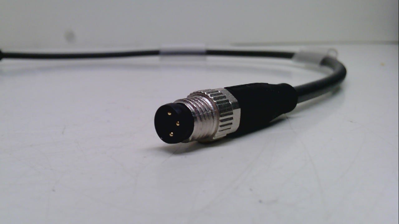
Figure 3.2: Close-up view of the male straight connector end of the cordset.
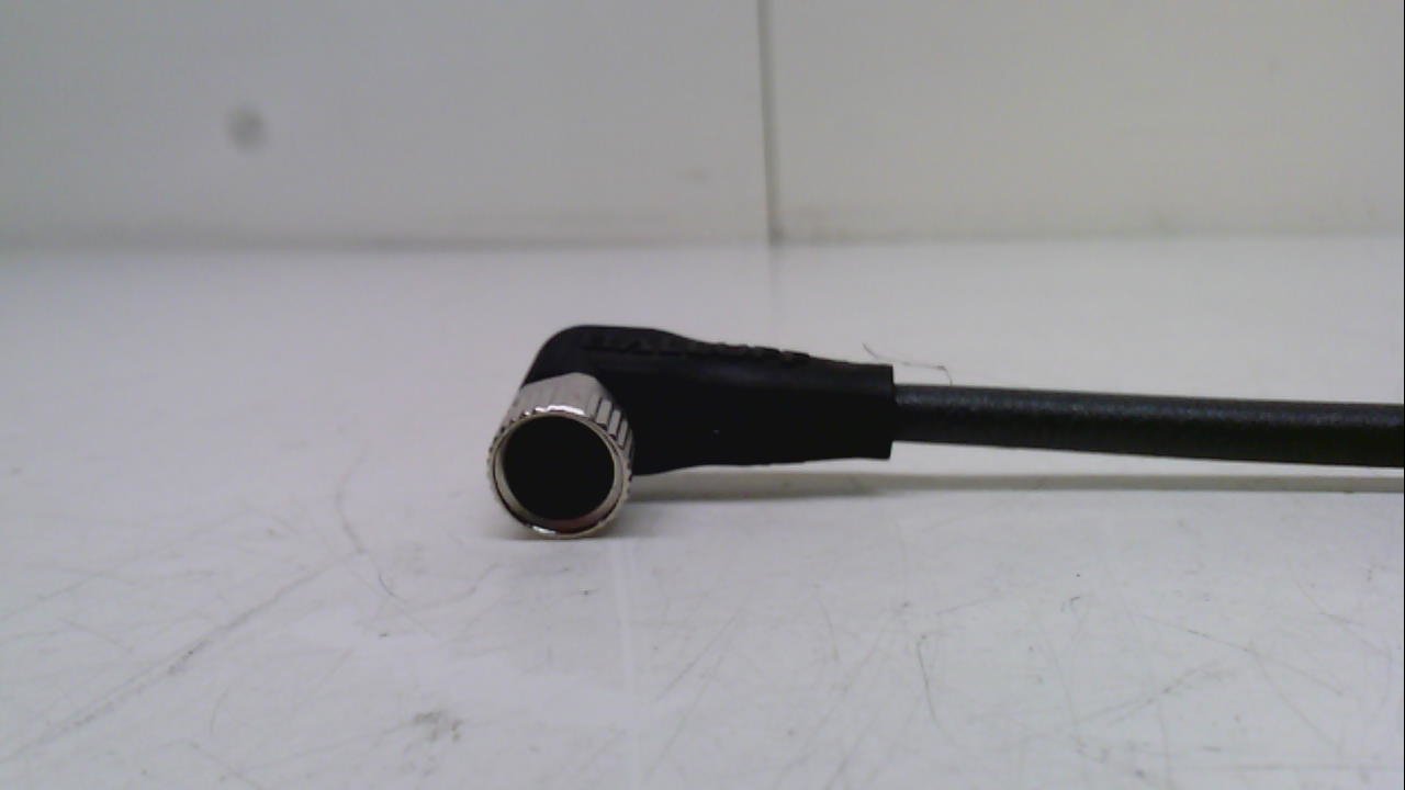
Figure 3.3: Close-up view of the female 90-degree connector end of the cordset.
Product Features:
- Weight: 0.33lb (0.15 Kilograms)
- Product Dimensions: 5.00 x 5.00 x 1.00 inches (packaged)
- Condition: New
4. Setup
- Power Disconnection: Before beginning installation, ensure that all power to the equipment or system where the cordset will be used is completely disconnected and locked out.
- Identify Connectors: Identify the male straight connector and the female 90-degree connector on the cordset.
- Connect Male End: Carefully align the male straight connector with the corresponding female port on your device or system. Push firmly until it clicks or is securely seated. For threaded connectors, gently twist the locking collar clockwise until hand-tight. Do not overtighten.
- Connect Female End: Align the female 90-degree connector with the corresponding male port. Ensure the pins are correctly aligned with the receptacles. Push firmly until it is securely seated. Twist the locking collar clockwise until hand-tight. The 90-degree angle allows for routing in tight spaces.
- Verify Connection: Visually inspect both connections to ensure they are fully engaged and the locking collars (if present) are tightened.
- Cable Routing: Route the cable in a manner that avoids sharp bends, pinching, or exposure to excessive heat or abrasive surfaces. Secure the cable if necessary to prevent accidental dislodgement.
- Power Reconnection: Once all connections are secure and verified, power can be reconnected to the system.
5. Operating
The Balluff Micro Cordset is a passive component designed to facilitate electrical connections between compatible devices. Once properly installed, its operation is integrated with the devices it connects.
- Ensure the cordset is not subjected to excessive pulling, twisting, or bending during operation.
- Monitor the connected system for proper functionality after installation.
- If the cordset is part of a moving system, ensure it has adequate slack and is protected from mechanical stress.
6. Maintenance
Regular inspection and light cleaning will help ensure the longevity and reliable performance of your cordset.
- Visual Inspection: Periodically inspect the entire length of the cordset, including connectors, for any signs of damage such as cuts, abrasions, cracks, or discoloration. Check for loose connections.
- Cleaning: If necessary, gently wipe the cordset and connectors with a clean, dry, lint-free cloth. For stubborn dirt, a cloth lightly dampened with water or a mild, non-abrasive cleaning solution can be used, ensuring the cordset is completely dry before reconnecting power. Do not use harsh chemicals or solvents.
- Storage: If the cordset is removed from service, store it in a clean, dry environment, away from direct sunlight and extreme temperatures. Avoid coiling it too tightly.
7. Troubleshooting
This section addresses common issues that may arise with the cordset.
| Problem | Possible Cause | Solution |
|---|---|---|
| No signal/power transmission | Loose connection; Damaged cable/connector; Incorrect pinout (unlikely for standard cordset) | Ensure both ends of the cordset are fully seated and locking collars are tightened. Inspect the cordset for visible damage. Replace if damaged. |
| Intermittent connection | Loose connection; Minor cable damage; Contamination in connector | Check and re-secure connections. Inspect cable for subtle damage. Clean connector pins if necessary (with power off). |
| Physical damage to cable/connector | Mechanical stress; Abrasion; Impact | Immediately disconnect power. Replace the cordset. Ensure proper cable routing to prevent future damage. |
If troubleshooting steps do not resolve the issue, contact Balluff technical support or a qualified technician.
8. Specifications
| Attribute | Value |
|---|---|
| Model Number | BCC M323-M313-30-300-PX0334-003 |
| Brand | Balluff |
| Product Dimensions (packaged) | 5 x 5 x 1 inches |
| Item Weight | 0.15 Kilograms (5.29 ounces) |
| Number of Poles | 3 |
| Connector Type 1 | Male Straight |
| Connector Type 2 | Female 90-Degree |
| Manufacturer | BALLUFF |
| Date First Available | July 7, 2015 |
9. Warranty and Support
For information regarding product warranty, please refer to the official Balluff warranty policy available on their website or contact their customer service directly. Specific warranty terms may vary based on region and purchase date.
Technical Support:
If you encounter issues that cannot be resolved using the troubleshooting guide, or require further technical assistance, please contact Balluff customer support. Have your product model number (BCC M323-M313-30-300-PX0334-003) and purchase information ready when contacting support.
You can typically find contact information for Balluff on their official website: www.balluff.com


