1. Introduction
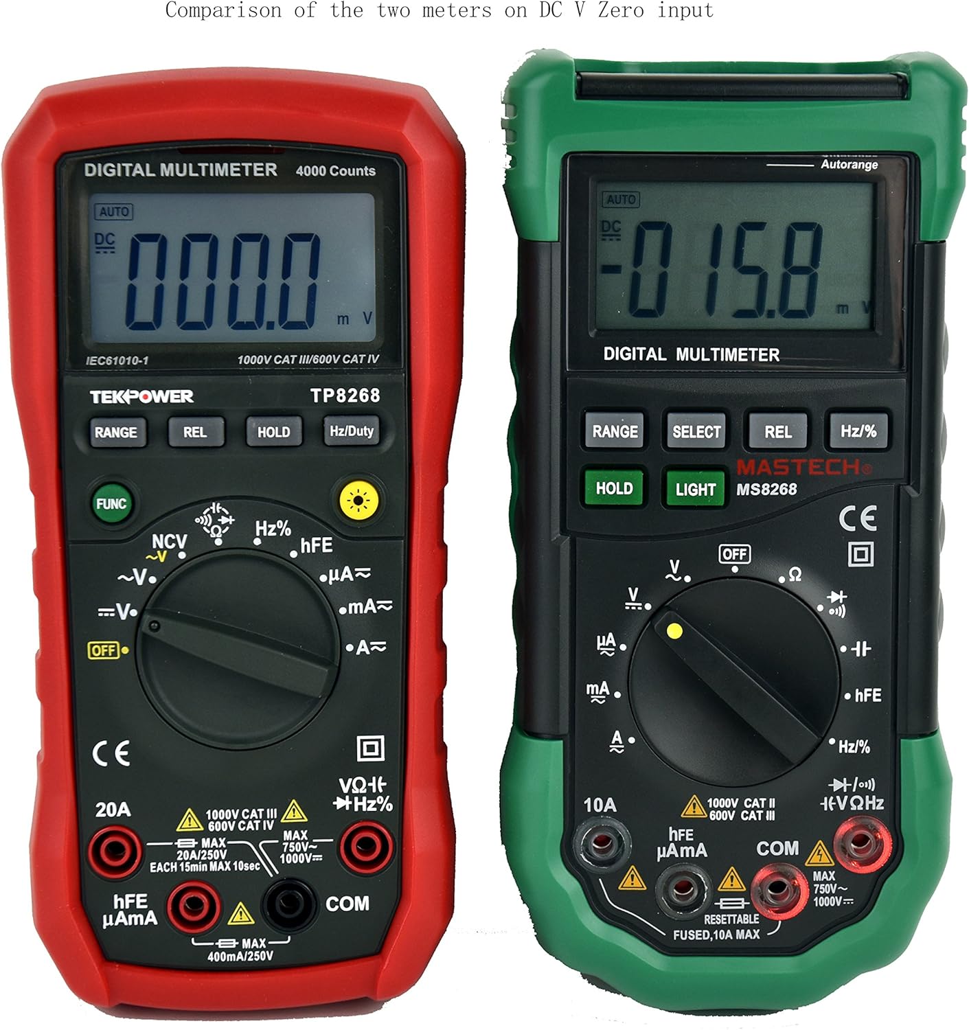
This manual provides detailed instructions for the safe and effective operation of your Tekpower TP8268 Digital Multimeter. The TP8268 is an advanced auto/manual ranging digital multimeter, featuring improved accuracy and additional functionalities compared to its predecessor, the MS8268. Key features include Non-Contact Voltage (NCV) detection and a blue LED back-lit LCD display. Please read this manual thoroughly before use.
2. Safety Information
Always observe safety precautions when using electrical testing equipment. Failure to do so may result in injury or damage to the meter or equipment under test.
- Ensure the meter is set to the correct function and range before making measurements.
- Do not attempt to measure voltages or currents exceeding the maximum rated values for the meter.
- Always disconnect power to the circuit before connecting or disconnecting test leads, especially when measuring current.
- Use caution when working with voltages above 30V AC RMS, 42V peak, or 60V DC, as these pose a shock hazard.
- Inspect test leads for damage before each use. Replace damaged leads immediately.
- Do not operate the meter if it appears damaged or if the case is open.
- Adhere to all local and national safety codes.
3. Package Contents
Verify that all items are present in your package:
- 1x Tekpower TP8268 Digital Multimeter
- 1x Pair of High Quality Test Leads (Red and Black)
- 1x Multi-function Adapter for hFE and Capacitance Test
- 1x 9V Battery (pre-installed or included separately)
- 1x User Manual

4. Product Overview and Features
The Tekpower TP8268 is designed for precision and ease of use in various electrical measurement tasks. Its robust design and comprehensive features make it suitable for both hobbyists and professionals.
- Auto/Manual Ranging: Automatically selects the appropriate measurement range or allows manual selection for specific applications.
- Non-Contact Voltage (NCV) Feature: Detects AC voltage above 110V RMS without direct contact, useful for identifying live wires.
- Blue LED Back-lit LCD Display: Provides clear readings in low-light conditions.
- Relative Measurement: Allows for comparison measurements against a stored reference value.
- Data Hold: Freezes the displayed reading for convenient recording.
- Diode Check: Tests the functionality of diodes.
- Continuity Test: Audible indication for circuit continuity (less than 60 ohms).
- hFE Test: Measures the DC current gain of transistors.
- Auto Power Off: Conserves battery life (can be disabled).

5. Setup
5.1. Battery Installation
- Ensure the multimeter is turned OFF.
- Locate the battery compartment on the back of the meter.
- Use a screwdriver to open the battery cover.
- Insert the 9V battery, observing the correct polarity (+/-).
- Replace the battery cover and secure it with the screw.
5.2. Connecting Test Leads
- Insert the black test lead into the "COM" (common) jack.
- For most voltage, resistance, and continuity measurements, insert the red test lead into the "VΩHz" jack.
- For current measurements up to 400mA, insert the red test lead into the "µAmA" jack.
- For current measurements up to 20A, insert the red test lead into the "20A" jack.
6. Operating Instructions
6.1. Turning On/Off and Function Selection
Rotate the central rotary switch to the desired measurement function to turn the meter ON. Turn the switch to "OFF" to power down the meter.
6.2. AC/DC Voltage Measurement
- Connect the black lead to COM and the red lead to VΩHz.
- Rotate the switch to the "V~" (AC Voltage) or "V-" (DC Voltage) position.
- The meter will automatically select the range. For manual ranging, press the RANGE button.
- Touch the test probes to the circuit points where voltage is to be measured.

6.3. AC/DC Current Measurement
- IMPORTANT: Disconnect power to the circuit before connecting the meter in series.
- Connect the black lead to COM. Connect the red lead to "µAmA" for small currents or "20A" for larger currents.
- Rotate the switch to the "A~" (AC Current) or "A-" (DC Current) position.
- Break the circuit and connect the meter in series with the load.
- Apply power to the circuit and read the current.
6.4. Resistance Measurement
- Connect the black lead to COM and the red lead to VΩHz.
- Rotate the switch to the "Ω" (Resistance) position.
- Ensure the circuit is de-energized before measuring resistance.
- Touch the probes across the component to measure its resistance.
6.5. Non-Contact Voltage (NCV) Detection
- Rotate the switch to the "NCV" position.
- Move the top tip of the meter near the conductor or outlet.
- The meter will emit an audible beep and the NCV indicator will light up if AC voltage is detected.

6.6. Other Functions (Diode, Continuity, hFE, Capacitance, Frequency)
Refer to the specific symbols on the rotary switch and the detailed specifications table for instructions on using Diode Check, Continuity, hFE, Capacitance, and Frequency/Duty Cycle measurements. Use the multi-function adapter for hFE and capacitance tests as needed.
7. Maintenance
7.1. General Care
- Keep the meter dry. If it gets wet, wipe it dry immediately.
- Use and store the meter in normal temperature environments. Extreme temperatures can shorten the life of electronic devices.
- Handle the meter gently and carefully. Dropping it can damage circuit boards and cases.
- Keep the meter away from dust and dirt, which can cause premature wear of parts.
- Wipe the meter with a damp cloth occasionally to keep it looking new. Do not use harsh chemicals, cleaning solvents, or strong detergents.
7.2. Battery Replacement
When the battery symbol appears on the display, replace the 9V battery as described in the Setup section (5.1). Always remove batteries if the meter is not going to be used for an extended period.
8. Troubleshooting
8.1. Display Shows "OL" (Overload)
If the display shows "OL" during a measurement, it indicates that the input value exceeds the selected range or the maximum measurement capability of the meter. Try selecting a higher range if available, or ensure the measured value is within the meter's specifications.
8.2. No Reading or Incorrect Reading
- Check battery level and replace if low.
- Ensure test leads are securely connected to the correct jacks.
- Verify the rotary switch is set to the appropriate function and range for the measurement.
- Inspect test leads for damage or breaks.
- Ensure proper contact between probes and the circuit under test.
9. Specifications
The following table outlines the key specifications for the Tekpower TP8268 Digital Multimeter:
| Measurement Type | Range | Accuracy |
|---|---|---|
| DC Voltage | 400mV/4V/40V/400V/1000V | ±(0.5%+3) |
| AC Voltage | 4V/40V/400V/750V | ±(1.2%+20) |
| DC Current | 400µA/4000µA/40mA/400mA/10A/20A | ±(1.2%+3) (up to 400mA), ±(1.5%+8) (10A), ±(2.0%+10) (20A) |
| AC Current | 400µA/4000µA/40mA/400mA/10A/20A | ±(1.5%+5) (up to 400mA), ±(2.0%+10) (10A), ±(2.0%+12) (20A) |
| Resistance | 400Ω/4kΩ/40kΩ/400kΩ/4MΩ/40MΩ | ±(1.0%+3) |
| Capacitance | 4nF/40nF/400nF/4µF/40µF/200µF | ±(5.0%+5) (up to 400nF), ±(4.0%+15) (4µF-200µF) |
| Frequency | 10Hz-200KHz | ±(1.5%+15) |
| Duty Cycle | 1%-99% | ±(2.0%+2) |
| Display | 4000 Counts | - |
| Power Supply | 9V Battery | - |
| Dimensions | 188mm x 92mm x 50mm | - |
| Weight | Approx. 370g | - |
| Safety Rating | CE CAT.III 1000V CAT.IV 600V RoHS | - |

10. Warranty and Support
The Tekpower TP8268 Digital Multimeter comes with a 1-year warranty in the USA. For technical support, warranty claims, or service inquiries, please contact Tekpower customer service through their official website or the retailer where the product was purchased.
For additional resources and product information, visit the Tekpower Store on Amazon.
11. Product Videos
Digital Multimeter 6000 Count by PROSTER US
This video provides an overview of a digital multimeter, demonstrating its features and basic operation, including NCV and continuity tests. While not specific to the TP8268, it illustrates general multimeter usage.