1. Introduction
The Waveshare Atmel-ICE Basic Kit is a powerful development tool designed for debugging and programming Atmel SAM and AVR microcontrollers that feature on-chip debug capabilities. This kit supports a wide range of interfaces including JTAG, SWD, PDI, TPI, aWire, SPI, and debugWIRE, making it versatile for various embedded development tasks. It is an essential tool for developers working with Atmel's ARM Cortex-M based SAM and AVR architectures.
2. Key Features
- Supports debugging and programming of Atmel ARM Cortex-M based Atmel SAM and AVR microcontrollers with on-chip debug capability.
- Compatible with JTAG, SWD, PDI, TPI, aWire, SPI, and debugWIRE interfaces.
- Utilizes all built-in hardware breakpoints available in the target microcontroller.
- Offers up to 128 software breakpoints for comprehensive debugging.
- Operates with target voltages from 1.62V to 5.5V.
- USB powered for convenience.
- Provides both ARM Cortex Debug Connector (10-pin) pin-out and AVR JTAG connector pin-out.
3. Components Included
The Waveshare Atmel-ICE Basic Kit (Atmel-ICE-B2) includes the following components:
- Atmel-ICE Unit
- USB Cable
- 10-pin 50-mil JTAG/SWD Cable
- 6-pin 100-mil AVR ISP/debugWIRE/PDI/aWire/TPI Cable
- Adapter Board
- 6-pin to 10-pin ISP Cable

Figure 1: Overview of the Waveshare Atmel-ICE Basic Kit components, including the Atmel-ICE unit, USB cable, various ribbon cables, and the adapter board.

Figure 2: Close-up view of the Atmel-ICE unit, a compact white device with blue accents and indicator lights.

Figure 3: Various connection cables and the blue adapter board included in the kit, essential for connecting to different target microcontrollers.
4. Setup and Connection
Proper connection of the Atmel-ICE to your target microcontroller is crucial for successful debugging and programming. The kit includes an adapter board and various cables to facilitate connections to different pin-outs.
4.1 Adapter Board Overview

Figure 4: Top view of the adapter board, showing various headers for different connection types.
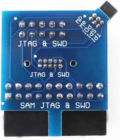
Figure 5: Bottom view of the adapter board, illustrating the pin labels for JTAG, SWD, PDI, SPI, TPI, aWire, and SAM JTAG/SWD interfaces.
4.2 Connection Options
The Atmel-ICE supports various connection configurations for SAM and AVR microcontrollers. Refer to the diagrams below for typical connection setups.

Figure 6: Detailed diagrams showing Atmel-ICE connection options for SAM and AVR targets, including pinout configurations for 10-pin AVR JTAG, 6-pin AVR ISP/debugWIRE/PDI/aWire/TPI, and 10-pin SAM JTAG/SWD headers.
Note:
- When connecting the adapter board to a target, pay attention to Pin 1 (indicated by a white spot or square solder pad).
- The adapter board included in Atmel-ICE-B2 is compatible with the official one in the Atmel-ICE Full Kit.
5. Supported Software and Devices
The Atmel-ICE is designed to work seamlessly with industry-standard development environments and supports a broad range of Atmel microcontrollers.

Figure 7: Information on supported software (e.g., Atmel Studio 6.2 or higher, ICCAVR, CVAVR, IAR) and a list of supported Atmel AVR and SAM devices for programming and debugging.
5.1 Supported Software
- Perfectly supports Atmel Studio 6.2 or higher version.
- Directly supports ICCAVR or higher version.
- Supports programming HEX files generated by ICCAVR, CVAVR, IAR, etc.
5.2 Supported Devices
- Programming and on-chip debugging of all Atmel AVR 32-bit MCUs on both JTAG and aWire interfaces.
- Programming and on-chip debugging of all Atmel AVR XMEGA® family devices on both JTAG and PDI 2-wire interfaces.
- JTAG and SPI programming and debugging of all Atmel AVR 8-bit MCUs with OCD support on either JTAG or debugWIRE interfaces.
- Programming and debugging of all Atmel SAM ARM Cortex-M based MCUs on both SWD and JTAG interfaces.
- Programming of all Atmel tinyAVR® 8-bit MCUs with support for the TPI interface.
6. Operating Instructions
Once the Atmel-ICE is physically connected to your target device and powered via USB, you can begin debugging or programming using your chosen Integrated Development Environment (IDE), such as Atmel Studio. The specific steps will vary depending on your IDE and the target microcontroller, but generally involve:
- Install Drivers: Ensure all necessary drivers for the Atmel-ICE are installed on your computer. These are typically included with Atmel Studio.
- Connect Atmel-ICE: Connect the Atmel-ICE unit to your computer via the USB cable and to your target board using the appropriate ribbon cable and adapter.
- Power Target: Ensure your target microcontroller board is powered correctly.
- Open IDE: Launch your development environment (e.g., Atmel Studio).
- Select Tool: In the IDE, select Atmel-ICE as your programming/debugging tool.
- Configure Project: Configure your project settings to match your target microcontroller and the desired interface (JTAG, SWD, etc.).
- Start Session: Initiate a debugging session or program the device as required by your project.
7. Maintenance
To ensure the longevity and reliable operation of your Atmel-ICE Basic Kit, follow these general maintenance guidelines:
- Keep Clean: Regularly clean the device and cables with a soft, dry cloth. Avoid using harsh chemicals or abrasive materials.
- Store Properly: Store the kit in a dry, dust-free environment when not in use.
- Handle with Care: Avoid dropping the device or subjecting it to physical shock. Do not pull cables by the wire; always grasp the connector.
- Avoid Moisture: Protect the device from moisture and extreme temperatures.
8. Troubleshooting
If you encounter issues with your Atmel-ICE Basic Kit, consider the following troubleshooting steps:
- Connection Check: Verify all cables are securely connected to the Atmel-ICE, the adapter board, and the target microcontroller. Ensure Pin 1 alignment is correct.
- Power Supply: Confirm that both the Atmel-ICE (via USB) and the target board are properly powered.
- Driver Installation: Ensure the latest drivers for the Atmel-ICE are installed on your computer. Reinstalling drivers can sometimes resolve connectivity issues.
- IDE Configuration: Double-check your IDE settings to ensure the correct programming/debugging tool (Atmel-ICE) and interface are selected for your target device.
- Target Voltage: Verify that the target microcontroller's operating voltage is within the Atmel-ICE's supported range (1.62V to 5.5V).
- Firmware Update: Check if a firmware update is available for your Atmel-ICE unit through your IDE.
- Consult Documentation: Refer to the official Atmel Studio documentation or Waveshare's online resources for specific error codes or advanced troubleshooting.
9. Specifications
Detailed technical specifications for the Waveshare Atmel-ICE Basic Kit:
| Feature | Detail |
|---|---|
| Brand | Waveshare |
| Model Number | Atmel-ICE-B2 |
| Interface Voltage | 1.62V – 5.5V |
| JTAG Clock | 32KHz – 7.5MHz |
| PDI Clock | 32KHz – 7.5MHz |
| debugWIRE Baudrate | 4Kbit/s – 0.5Mbit/s |
| aWire Baudrate | 7.5Kbit/s – 7Mbit/s |
| SPI Clock | 8KHz – 5MHz |
| SWD Clock | 32KHz – 2MHz |
| PC Interface | USB 2.0 high speed |
| Connectivity Technology | USB |
| Operating System Compatibility | Linux (and typically Windows with Atmel Studio) |
| Item Weight | 0.01 ounces |
| Product Dimensions (LxWxH) | 7.09 x 3.94 x 3.54 inches |
| Manufacturer | Waveshare |
10. Development Resources
For additional information, detailed guides, and community support, please visit the official Waveshare Wiki page for Atmel-ICE:
11. Selection Guide
The Atmel-ICE series offers different kits. The Atmel-ICE Basic Kit (Atmel-ICE-B2) provides essential functionality. For a comparison of the different Atmel-ICE versions, refer to the guide below:

Figure 8: Comparison table illustrating the components included in Atmel-ICE, Atmel-ICE-B2 (Basic Kit), and Atmel-ICE-C versions.
- Atmel-ICE: Includes everything in the official Atmel-ICE Full Kit, plus an extra free 6-pin to 10-pin ISP cable.
- Atmel-ICE-B2: Includes everything in the official Atmel ICE Basic Kit, and more adapter and cables from Waveshare, provides the same functions as Atmel-ICE Full Kit in lower price.
12. Warranty and Support
For warranty information and technical support, please refer to the official Waveshare website or contact their customer service directly. Keep your purchase receipt as proof of purchase for any warranty claims.


