
1. Introduction
This manual provides comprehensive instructions for the operation, maintenance, and parts identification of the Kalamazoo Freedom Series, FA 350 SA Circular Saws. It is essential that all personnel involved in the operation or supervision of this machine read and understand the contents of this manual before use. Special attention should be given to the safety procedures outlined herein.
This manual covers the following models: Freedom Series, FA 350, M, PV, SA, and A. It includes detailed information on machine setup, operator controls, machine operation, blade selection, cutting guides, maintenance, troubleshooting, parts breakdowns, technical data, electrical schematics, and wiring diagrams. The manual contains 133 printed pages of essential information.
1.1 Safety Precautions
Always prioritize safety when operating or maintaining the circular saw. Familiarize yourself with all safety warnings and instructions provided in this manual. Failure to follow safety guidelines can result in serious injury or damage to the equipment.
- Ensure all safety guards are in place and functioning correctly before operation.
- Wear appropriate personal protective equipment (PPE), including eye protection, hearing protection, and safety gloves.
- Disconnect power before performing any maintenance, adjustments, or cleaning.
- Never operate the machine under the influence of drugs or alcohol.
- Keep the work area clean and well-lit.
1.2 Descriptions and Specifications
Detailed descriptions of the machine components and their functions are provided throughout this manual. Technical specifications, including dimensions, power requirements, and operational capacities, are listed in the "Specifications" section.
1.3 Warranty Information
Information regarding the product warranty, including terms, conditions, and duration, is typically provided with the purchase documentation. Please refer to your sales agreement or contact Kalamazoo customer service for specific warranty details.
1.4 Returned Goods Policy
For information on returning parts or the complete machine, please consult the original purchase agreement or contact Kalamazoo customer support. All returns must adhere to the company's established returned goods policy.
2. Machine Setup
Proper setup is crucial for the safe and efficient operation of your Kalamazoo circular saw. Follow these steps carefully.
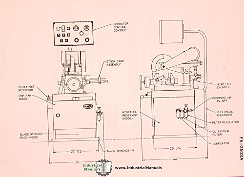
Figure 2.1: Diagram illustrating the main components of the Kalamazoo FA-350SA Circular Saw, including the Operator Control Console, Stock Stop Assembly, Spray Mist Reservoir, Chip Pan, Blade Storage Rack, Hydraulic Reservoir, Head Lift Cylinder, Incoming Air, Electrical Enclosure, Filter/Regulator, Oil Removal Filter, and Lubricator.
2.1 Machine Installation
Install the machine on a level, stable surface capable of supporting its weight and the weight of the material being cut. Ensure adequate clearance around the machine for safe operation and maintenance.
2.2 Power Connection
Connect the machine to a power supply that matches the voltage and phase requirements specified on the machine's nameplate. Consult a qualified electrician for proper wiring and grounding.
2.3 Spray Mist/Flood Coolant System
If equipped, fill the spray mist or flood coolant reservoir with the recommended coolant. Ensure all lines are properly connected and free of leaks. This system helps to cool the blade and workpiece during cutting.
2.4 Changing Operating Voltages
Refer to the electrical schematics in the "Specifications" section for instructions on changing the operating voltage. This procedure should only be performed by qualified personnel.
2.5 Service Drawings
Detailed service drawings are provided in the "Specifications" section to assist with installation and maintenance procedures.
2.6 Installing Optional Equipment
Follow the specific instructions provided with any optional equipment for proper installation and integration with the main machine.
3. Operator Controls
This section details the various operator controls and their functions for different models.
3.1 M and PV Models
Specific controls for M and PV models typically include power on/off, blade activation, feed rate adjustment, and emergency stop buttons. Refer to the control panel diagram for exact button functions.
3.2 SA Models
SA models feature an operator control console with specific buttons and indicators for functions such as automatic cutting cycles, material clamping, and coolant activation. Consult the control panel layout for detailed operation.
3.3 A Models
A models may include advanced controls for automated processes, such as programmable cut lengths and integrated material handling. Detailed instructions for these controls are provided in this section.
4. Machine Operation
This section outlines the procedures for operating the Kalamazoo circular saw safely and effectively.
4.1 M and PV Models Operation
To operate M and PV models, ensure the workpiece is securely clamped, select the appropriate blade speed, and initiate the cut using the designated controls. Monitor the cutting process and adjust feed rate as necessary.
4.2 SA Models Operation
SA models often feature semi-automatic operation. Load the material, engage the clamp, and press the start button. The machine will perform the cut and return to its home position. Always ensure the cutting path is clear.
4.3 A Models Operation
A models are designed for automated operation. Program the desired cut parameters, load the material into the barfeed system, and initiate the cycle. Supervise the automated process to ensure proper function and safety.
4.4 Optional Equipment Operation
Refer to the specific instructions provided with any optional equipment for their operational procedures. This may include additional clamping devices, material handling systems, or specialized cutting attachments.
4.5 Angle Cutting
Instructions for setting up and performing angle cuts are detailed here. Ensure the workpiece is securely clamped and the blade angle is correctly set before initiating the cut. Use the angle adjustment mechanism and lock it firmly in place.
4.6 Blade Selection and Cutting Guide
Selecting the correct blade is critical for optimal cutting performance and blade longevity. The type of material being cut dictates the appropriate blade material, tooth count, and geometry.
- Blade Selection: Choose blades appropriate for the material being cut, considering factors like hardness, thickness, and desired finish.
- Non-Ferrous Cutting: Use specific blades designed for aluminum, brass, copper, and other non-ferrous metals. These typically have a higher tooth count and specific tooth geometry to prevent material loading.
- Ferrous Cutting: Use specific blades designed for steel, iron, and other ferrous metals. These blades are typically made from high-speed steel or carbide-tipped materials and have fewer, stronger teeth.
4.7 Sawing Controls
Familiarize yourself with the sawing controls, including blade speed adjustment, feed rate control, and clamping mechanisms. Proper adjustment of these controls will optimize cutting efficiency and blade life.
4.8 Cutting Guide
Utilize the cutting guide to ensure accurate and straight cuts. Adjust the guide according to the dimensions of your workpiece and lock it securely before starting the cut.
4.9 Blade Changing
Always disconnect power before changing the blade. Follow the step-by-step instructions for safely removing the old blade and installing a new one. Ensure the blade is correctly oriented, tensioned, and securely fastened to prevent accidents.
4.10 Cutting Tips
To optimize cutting performance and extend blade life: ensure the workpiece is always securely clamped; use appropriate coolant; maintain consistent feed pressure; and avoid forcing the cut. Regularly inspect the blade for wear or damage.
5. Maintenance
Regular maintenance is essential to ensure the longevity and optimal performance of your Kalamazoo circular saw. Always disconnect power and follow lockout/tagout procedures before performing any maintenance.
5.1 Lubrication Specifications, Locations, Schedule
Refer to the lubrication chart provided in the full manual for recommended lubricants, specific lubrication points on the machine, and the required frequency of application. Proper lubrication prevents premature wear of moving parts.
5.2 Air System Maintenance
Regularly check and drain moisture from the air filter/regulator to prevent contamination of pneumatic components. Inspect air lines for leaks and ensure proper air pressure is maintained for optimal performance of pneumatic cylinders and controls.
5.3 Cylinder Maintenance/Repair
Inspect hydraulic or pneumatic cylinders for leaks, scoring, or damage to seals. Clean cylinder rods regularly. If repair is necessary, refer to the parts breakdown for replacement procedures and use only genuine Kalamazoo parts.
5.4 Directional Valve Maintenance/Repair
Check directional valves for proper operation, ensuring smooth and precise control of hydraulic or pneumatic flow. Clean or replace as needed, referring to the relevant diagrams in the manual for correct reassembly.
5.5 Coolant System Maintenance
Clean the coolant reservoir and filter regularly to prevent sludge buildup and maintain coolant quality. Replace coolant as per manufacturer recommendations to prevent bacterial growth, extend blade life, and ensure efficient cooling.
5.6 Vise Maintenance
Keep the vise jaws clean and free of debris. Lubricate the vise screw and sliding surfaces regularly to ensure smooth operation and secure clamping of workpieces. Check for wear on the jaws and replace if necessary.
5.7 Changing Drive Belts (FA Models)
For FA models, regularly inspect drive belts for signs of wear, cracking, or fraying. Check belt tension and adjust as necessary. Replace worn belts following the step-by-step instructions provided in the manual to maintain optimal power transmission.
5.8 Gearbox Maintenance (FS Models)
For FS models, check gearbox oil levels periodically and change the oil according to the maintenance schedule. Use only the specified type of gearbox oil. Listen for unusual noises that may indicate worn gears or bearings.
5.9 Barfeed Maintenance (-A Models)
For -A models equipped with barfeed systems, ensure the barfeed mechanism is clean, free of obstructions, and properly lubricated. Check for proper alignment and function of all moving parts to ensure smooth material feeding.
5.10 Electrical System Repair
Any electrical system inspections, troubleshooting, or repairs should only be performed by certified and qualified electricians. Always disconnect power at the main breaker and follow proper lockout/tagout procedures. Refer to the electrical schematics for accurate diagnosis and repair.
6. Troubleshooting
This section provides a guide to common operational issues and their potential solutions. If a problem persists after following these steps, contact Kalamazoo customer support for further assistance.
| Problem | Possible Cause | Solution |
|---|---|---|
| Machine does not start | No power supply; Emergency stop engaged; Safety interlock open; Motor overload tripped | Check main power connection; Reset emergency stop button; Ensure all safety guards are closed; Reset motor overload protector |
| Poor cut quality (rough finish, excessive burr) | Dull or damaged blade; Incorrect blade type for material; Improper feed rate or blade speed; Loose workpiece clamping | Replace or sharpen blade; Select correct blade for material; Adjust feed rate and blade speed; Secure workpiece firmly in vise |
| Excessive vibration or unusual noise | Loose mounting bolts; Worn bearings; Unbalanced or damaged blade; Misaligned components | Tighten all machine mounting fasteners; Inspect and replace worn bearings; Check blade for damage/balance; Verify component alignment |
| Coolant system not working properly | Low coolant level; Clogged filter or nozzle; Coolant pump malfunction; Air in lines | Refill coolant reservoir; Clean filter and clear nozzle obstructions; Inspect coolant pump for operation; Bleed air from coolant lines |
| Blade stalls during cut | Overload; Dull blade; Incorrect feed rate; Insufficient motor power | Reduce feed rate; Replace blade; Adjust feed rate to material; Verify power supply meets requirements |
7. Specifications
This section provides detailed technical data, parts breakdowns, and electrical information crucial for the proper understanding and maintenance of the Kalamazoo Freedom Series circular saws.
7.1 Technical Data
Detailed technical specifications for the FA 350 SA and other Freedom Series models are provided, including but not limited to: motor power (HP/kW), blade diameter capacity (inches/mm), maximum cutting capacities (round, square, rectangular), machine dimensions (length, width, height), weight, and operating voltage requirements. These specifications are vital for installation planning and operational limits.
7.2 Electrical Schematics
Complete electrical schematics and detailed wiring diagrams are included to assist with the installation, troubleshooting, and repair of the machine's electrical system. These diagrams illustrate the layout of circuits, components, and connections, and are indispensable for qualified electricians performing any electrical work on the saw.
7.3 Wiring Diagrams
Detailed wiring diagrams illustrate the physical connections between all electrical components, including motors, switches, sensors, and control panels. These diagrams ensure correct wiring for safe and efficient operation and are essential for diagnosing electrical faults.
7.4 Parts Breakdowns
Exploded view diagrams and corresponding parts lists are provided for easy identification and ordering of replacement parts. Each component is numbered for clear reference, allowing users to accurately identify and procure the correct parts for maintenance and repair.
8. Support
For further assistance, technical support, or to order replacement parts, please contact Kalamazoo customer service. When contacting support, please have your machine's model number (e.g., FA 350 SA) and serial number ready to expedite service.
Note: This digital manual is a quality-bound copy of the original. For the most up-to-date information, always refer to the latest official documentation from Kalamazoo or visit their official website.