1. Introduction
This manual provides essential information for the safe and effective use of the VEMER VE755600 Digital Multifunction Tester. This device is designed for comprehensive electrical measurements, including continuity, insulation, loop impedance, short circuit analysis, differential current, earth resistance, AC voltage, and phase sequence detection. Please read this manual thoroughly before operating the instrument and retain it for future reference.
2. Safety Information
Always adhere to local and national safety regulations when using this instrument. Failure to follow safety precautions can result in electric shock, injury, or damage to the device.
- Do not use the tester if it appears damaged or if the test leads are compromised.
- Do not attempt to measure voltages or currents exceeding the specified maximum ratings.
- Ensure proper insulation and grounding when performing measurements.
- Always disconnect power to the circuit before making connections for resistance or continuity tests.
- Wear appropriate personal protective equipment (PPE), such as insulated gloves and safety glasses.
- Avoid operating the device in wet or damp conditions.
3. Product Overview
The VEMER VE755600 is a robust digital multifunction tester equipped with an internal memory for storing measurement results and a USB interface for PC connectivity. It is designed for professional use in electrical installations.
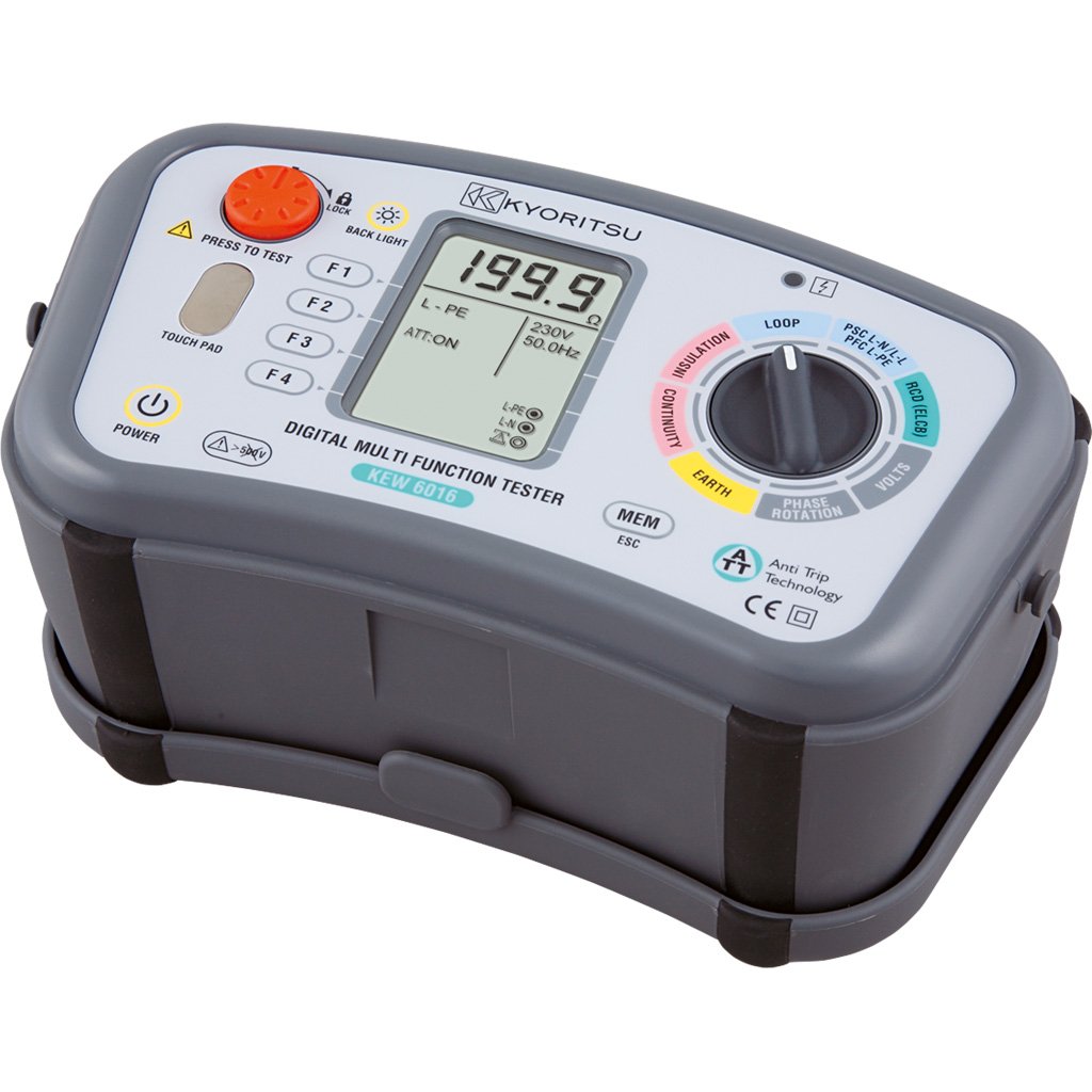
Figure 3.1: VEMER VE755600 Digital Multifunction Tester. This image displays the front view of the dark gray multifunction tester, showing its display screen, rotary selector switch, and various function buttons. Test lead input jacks are visible at the bottom.
Key Features:
- Measures continuity, insulation resistance, loop impedance, short circuit current, differential current, earth resistance, AC voltage, and phase sequence.
- Internal memory for saving measurement data.
- USB interface for data transfer to a personal computer.
- Compact and durable design for field use.
4. Setup
Before using the VEMER VE755600, ensure it is properly prepared for operation.
4.1 Battery Installation
- Locate the battery compartment on the rear of the device.
- Open the compartment cover using a suitable tool (e.g., screwdriver).
- Insert the required batteries, observing correct polarity (+/-).
- Close the battery compartment cover securely.
4.2 Connecting Test Leads
- Identify the appropriate input jacks for your desired measurement (e.g., COM, VΩmA, etc.).
- Insert the test leads firmly into the corresponding jacks.
- Ensure the test probes are clean and free from damage.
5. Operating Instructions
This section details the procedures for performing various measurements with the VEMER VE755600.
5.1 Powering On/Off
To power on the device, rotate the selector switch to any measurement function. To power off, rotate the selector switch to the 'OFF' position.
5.2 Continuity Measurement
- Ensure the circuit under test is de-energized.
- Rotate the selector switch to the Continuity position (often indicated by a speaker or ohm symbol).
- Connect the test leads across the component or conductor to be tested.
- Read the resistance value on the display. An audible tone typically indicates low resistance (continuity).
5.3 Insulation Resistance Measurement
- Ensure the circuit under test is de-energized and isolated.
- Rotate the selector switch to the Insulation position (often indicated by MΩ).
- Select the desired test voltage (e.g., 250V, 500V, 1000V) if applicable.
- Connect the test leads between the conductor and earth, or between two conductors.
- Press the 'TEST' button and hold until the measurement stabilizes.
- Read the insulation resistance value on the display.
5.4 Loop and Short Circuit Measurement
- Ensure the circuit is energized for this test.
- Rotate the selector switch to the Loop or Short Circuit position.
- Connect the test leads to the live, neutral, and earth terminals of the circuit.
- Initiate the test as per the device's instructions (e.g., press 'TEST').
- The display will show the loop impedance or prospective short circuit current.
5.5 Earth Resistance (Terra) Measurement
- Ensure the circuit is de-energized and isolated from the main supply.
- Rotate the selector switch to the Earth Resistance position (often indicated by RE or a ground symbol).
- Connect the test leads and auxiliary electrodes according to the chosen measurement method (e.g., 3-pole or 4-pole method). Refer to specific diagrams in the full manual for correct connections.
- Initiate the test and read the earth resistance value.
5.6 AC Voltage and Phase Sense Measurement
- Rotate the selector switch to the AC Voltage (V~) or Phase Sense position.
- For AC Voltage: Connect the test leads in parallel across the voltage source.
- For Phase Sense: Connect the test leads to the phases to determine their sequence.
- Read the voltage or phase sequence indication on the display.
5.7 Data Storage and PC Connection
The VE755600 features internal memory for storing measurement results. Consult the full product manual for detailed instructions on saving, recalling, and deleting data. To transfer data to a PC, connect the device via the USB interface and use the provided software (if applicable).
6. Maintenance
Proper maintenance ensures the longevity and accuracy of your VEMER VE755600.
6.1 Cleaning
Wipe the instrument's casing with a soft, damp cloth. Do not use abrasive cleaners or solvents. Ensure the device is powered off and disconnected from any circuits before cleaning.
6.2 Battery Replacement
Replace batteries when the low battery indicator appears on the display. Use only the specified battery type. Dispose of old batteries responsibly according to local regulations.
6.3 Storage
When not in use, store the tester in a dry, cool place, away from direct sunlight and extreme temperatures. If storing for extended periods, remove the batteries to prevent leakage.
7. Troubleshooting
If you encounter issues with your VEMER VE755600, refer to the following common problems and solutions.
- Device does not power on: Check battery installation and charge level. Replace batteries if necessary.
- Inaccurate readings: Ensure test leads are properly connected and not damaged. Verify the correct measurement function is selected. Calibrate the device if required (refer to service information).
- Display shows 'OL' (Overload): The measured value exceeds the device's range. Disconnect immediately and re-evaluate the circuit.
- No data transfer to PC: Check USB cable connection and ensure the correct software drivers are installed on your computer.
For persistent issues, contact VEMER customer support or an authorized service center.
8. Specifications
The following table outlines the technical specifications for the VEMER VE755600 Digital Multifunction Tester.
| Specification | Value |
|---|---|
| Brand | VEMER |
| Model Number | VE755600 |
| Product Dimensions (L x W x H) | 23.5 x 11.4 x 13.6 cm |
| Item Weight | 4.6 Kilograms |
| Power Source | Battery Powered |
| Style | Digital |
| Colour | darkgray |
| Global Trade Identification Number (GTIN) | 08007951126324 |
9. Warranty and Support
For detailed warranty information, please refer to the warranty card included with your product or visit the official VEMER website. Warranty terms and conditions may vary by region and retailer.
For technical support, service, or inquiries regarding your VEMER VE755600, please contact your authorized VEMER dealer or the manufacturer's customer service department. Keep your purchase receipt and product model number (VE755600) readily available when seeking support.


