1. Introduction
This manual provides essential information for the safe and effective operation of the OWON SDS5052E 50MHz Digital Storage Oscilloscope. It covers product overview, setup procedures, operational guidelines, maintenance, and troubleshooting tips. Please read this manual thoroughly before using the device to ensure proper functionality and to prevent damage.
2. Safety Information
Always observe the following safety precautions to prevent injury and damage to the instrument:
- Power Source: Connect the oscilloscope only to a power source with the specified voltage and frequency.
- Grounding: Ensure the instrument is properly grounded to prevent electric shock.
- Probes: Use only probes rated for the voltage and current being measured. Do not exceed the maximum input voltage specified for the oscilloscope.
- Environment: Operate the oscilloscope in a dry, well-ventilated area, away from direct sunlight, high temperatures, and excessive dust.
- Maintenance: Refer all servicing to qualified personnel. Do not attempt to open or repair the instrument yourself.
- Cleaning: Disconnect power before cleaning. Use a soft, damp cloth; avoid abrasive cleaners or solvents.
3. Product Overview
The OWON SDS5052E is a 50MHz Digital Storage Oscilloscope featuring a clear 8-inch color LCD display. It offers a real-time sample rate of 500MS/s and a 10K record length, making it suitable for various electrical measurement tasks. Key features include a Pass/Fail function and user-defined measurement menus.
3.1 Front Panel
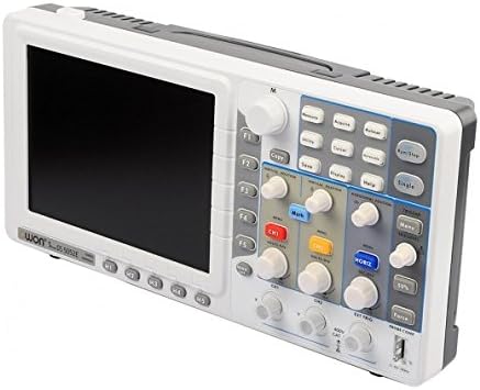
Figure 3.1: Front view of the SDS5052E Oscilloscope.
The front panel features the 8-inch TFT color display, function buttons (F1-F5), navigation controls, and dedicated sections for Vertical, Horizontal, and Trigger settings. Input channels CH1, CH2, and EXT TRIG are located at the bottom.

Figure 3.2: Close-up of the control panel.
The control panel includes buttons for Measure, Acquire, Autoset, Run/Stop, Save, Display, Help, and Utility. Rotary encoders allow fine adjustment of vertical position, volts/division, horizontal position, and seconds/division.
3.2 Rear Panel
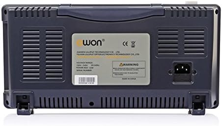
Figure 3.3: Rear view of the SDS5052E Oscilloscope.
The rear panel houses the AC power input connector and ventilation grilles for heat dissipation. A product label with model and serial number information is also present.
3.3 Side Panel (Connectivity)
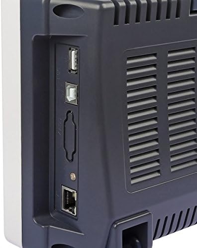
Figure 3.4: Side panel with connectivity ports.
The side panel provides various connectivity options, including USB ports for data transfer and device control, and a LAN port for network connectivity.
4. Setup
4.1 Unpacking and Inspection
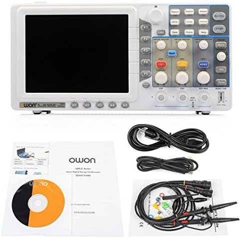
Figure 4.1: Package contents.
Carefully unpack the oscilloscope and all accessories. Verify that all items listed in the packing list are present and undamaged. The standard package includes the SDS5052E oscilloscope unit, two passive probes, a power cord, a USB cable, and a quick guide/CD.
4.2 Power Connection
- Ensure the oscilloscope's power switch is in the OFF position.
- Connect the provided power cord to the AC power input on the rear panel of the oscilloscope.
- Plug the other end of the power cord into a grounded AC power outlet.
4.3 Probe Connection and Compensation
- Connect the BNC connector of a passive probe to either the CH1 or CH2 input on the front panel.
- Attach the probe tip to the probe compensation test point (usually a small metal loop or pin labeled "PROBE COMP" or similar) on the front panel.
- Connect the probe's ground clip to the ground terminal next to the probe compensation test point.
- Power on the oscilloscope.
- Press the Autoset button. A square wave should appear on the screen.
- Adjust the compensation screw on the probe body using a non-metallic tool until the square wave corners are flat (neither overshot nor undershot).
5. Operating Instructions
5.1 Basic Measurements
- Vertical Controls: Use the VOLTS/DIV knob for the selected channel (CH1 or CH2) to adjust the vertical scale (voltage per division). Use the VERTICAL POSITION knob to move the waveform up or down.
- Horizontal Controls: Use the SEC/DIV knob to adjust the horizontal scale (time per division). Use the HORIZONTAL POSITION knob to move the waveform left or right.
- Autoset: Press the Autoset button to automatically adjust the vertical, horizontal, and trigger settings to display a stable waveform.
5.2 Triggering
Triggering stabilizes repetitive waveforms. The SDS5052E supports Edge, Pulse, Video, and Slope trigger types.
- Press the MENU button in the Trigger section to access trigger settings.
- Select the desired trigger type (e.g., Edge).
- Adjust the TRIG LEVEL knob to set the voltage level at which the trigger occurs. The trigger level indicator on the screen will move accordingly.
- Use the 50% button for quick adjustment to the 50% level of the waveform.
5.3 Measurement Functions
The oscilloscope provides automatic measurement functions.
- Press the Measure button to display the measurement menu.
- Use the function buttons (F1-F5) to select and add/remove desired measurements (e.g., Vpp, Vmax, Frequency, Period).
- The results will be displayed on the screen.
5.4 Saving Data
Waveforms and settings can be saved to internal memory or a USB flash drive.
- Insert a USB flash drive into the USB host port on the side panel (if saving externally).
- Press the Save button.
- Select the save type (e.g., Waveform, Setup, Image) and destination using the menu options.
- Confirm the save operation.
6. Maintenance
6.1 Cleaning
To clean the instrument, disconnect it from all power sources and wipe the exterior surfaces with a soft, damp cloth. Do not use abrasive cleaners, solvents, or harsh chemicals, as these may damage the casing or display. Ensure no moisture enters the ventilation openings.
6.2 Storage
When not in use for extended periods, store the oscilloscope in a clean, dry environment, protected from extreme temperatures and humidity. It is recommended to keep the original packaging for safe storage and transport.
6.3 Calibration
The oscilloscope is factory calibrated. For continued accuracy, periodic calibration by qualified service personnel is recommended, especially after significant temperature changes or prolonged use.
7. Troubleshooting
| Problem | Possible Cause | Solution |
|---|---|---|
| No display after power on | Power cord not connected; Power switch off; Faulty power supply | Check power cord connection; Ensure power switch is ON; Contact service if power supply is suspected. |
| No waveform displayed | Input signal too small/large; Incorrect vertical/horizontal settings; Trigger not set correctly; Probe not connected | Press Autoset; Adjust VOLTS/DIV and SEC/DIV; Check trigger level and source; Verify probe connection. |
| Unstable waveform | Incorrect trigger settings; No trigger source; Noise in signal | Adjust trigger level; Select appropriate trigger source and type; Use averaging mode to reduce noise. |
| Incorrect measurements | Probe attenuation factor incorrect; Oscilloscope not calibrated | Ensure probe attenuation setting matches the physical probe (e.g., 1X, 10X); Consider professional calibration. |
8. Specifications
The following are the key technical specifications for the OWON SDS5052E Digital Storage Oscilloscope:
- Bandwidth: 50MHz
- Sample Rate (real time): 500MS/s
- Horizontal Scale (s/div): 5ns/div to 100s/div (step by 1-2-5)
- Rise Time (at input, typical): ≤7ns
- Channel: 2 + 1 (external)
- Display: 8" color LCD, TFT display, 800 × 600 pixels, 65535 colors
- Input Impedance: 1MΩ ± 2%, in parallel with 15pF±5pF
- Channel Isolation: 50Hz : 100 : 1, 10MHz : 40 : 1
- Max Input Voltage: 400V (PK - PK) (DC+AC, PK - PK)
- DC Gain Accuracy: ±3%
- Record Length: 10K (optional 100K, 10M)
- DC Accuracy (average): Average≥16: ±(3% reading + 0.05 div) for ΔV
- Probe Attenuation Factor: 1X, 10X, 100X, 1000X
- LF Respond (AC, -3dB): ≥10Hz (at input, AC coupling, -3dB)
- Sample Rate / Relay Time Accuracy: ±100ppm
- Interpolation: sin(x)/x
- Interval (ΔT) Accuracy (full bandwidth): Single: ±(1 interval time + 100ppm × reading + 0.6ns), Average>16: ±(1 interval time + 100ppm × reading + 0.4ns)
- Input Coupling: DC, AC, and GND
- Vertical Resolution (A/D): 8 bits (2 Channels simultaneously)
- Vertical Sensitivity: 5mV/div to 10V/div (at input)
- Trigger Type: Edge, Pulse, Video, Slope, Alternate
- Parcel Dimensions: 42.67 x 23.88 x 12.45 cm
- Item Weight: 2.15 kg
9. Warranty and Support
For warranty information and technical support, please refer to the documentation provided with your product or contact OWON customer service directly. Keep your purchase receipt and product serial number handy when seeking support.


