
1. Introduction
The GoolRC FS-iA6B is a 6-channel receiver designed for use with Flysky i4, i6, and i10 transmitters. It operates on a reliable, interference-free 2.4GHz AFHDS2A signal, ensuring stable performance for your remote-controlled models. Its ultra-lightweight design and compact dimensions make it suitable for various applications, including airplanes, gliders, and helicopters. The receiver features PPM output and an iBus port, offering versatile connectivity options.
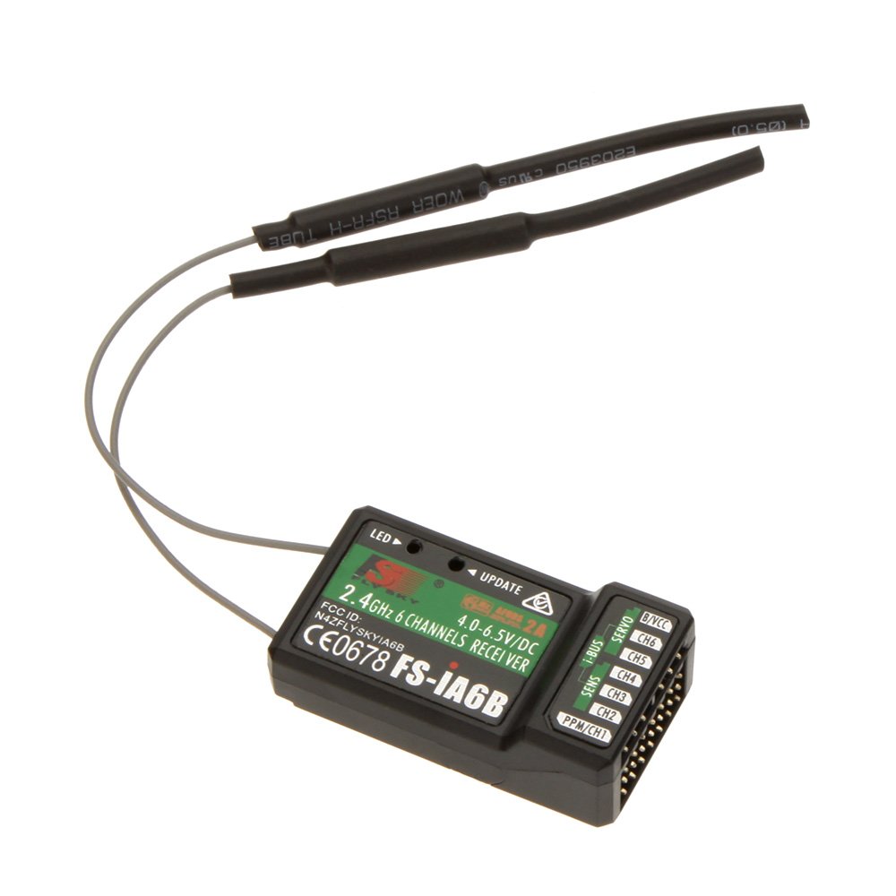
Image 1.1: The GoolRC FS-iA6B 6-Channel Receiver as packaged.
2. Safety Information
Please read and understand all instructions before operating the receiver. Failure to do so may result in damage to the product or personal injury.
- Ensure the receiver is correctly connected to your model's electronic speed controller (ESC) and servos. Incorrect wiring can cause malfunctions.
- Verify that the power supply to the receiver is within the specified voltage range (4.0-8.4V DC). Exceeding this range can damage the unit.
- Always perform a range check before operating your model to ensure a stable connection between the transmitter and receiver.
- Keep the receiver away from moisture, extreme temperatures, and strong electromagnetic fields.
- Do not attempt to modify or disassemble the receiver. This will void the warranty and may lead to unsafe operation.
3. Package Contents
Upon opening the package, please verify that all components are present and in good condition:
- 1x GoolRC Flysky FS-iA6B 6-Channel Receiver
- 1x Bind Cable

Image 3.1: The FS-iA6B receiver with its dual antennas and included bind cable.
4. Product Specifications

Image 4.1: Visual representation of the FS-iA6B receiver's dimensions and specifications.
| Feature | Detail |
|---|---|
| Product Model | FS-iA6B |
| PWM Channels | 6 |
| Wireless Frequency | 2.4GHz |
| Wireless Protocol | AFHDS 2A |
| Range | 500 ~ 1500m (in the air) |
| Antenna Type | Dual copper tube antenna (150mm*2) |
| Power Input | 4.0-8.4V DC |
| RSSI | Supported |
| Data Port | PWM / PPM / i.bus / s.bus |
| Temperature Range | -10 °C ~ +60 °C |
| Humidity Range | 20% - 95% |
| Online Update | Yes |
| Dimensions | 47mm (L) x 26.2mm (W) x 15mm (H) |
| Weight | 10g |
| Certification | CE, RCM |
| FCC ID | N4ZFLYSKYIA10 |
5. Setup and Binding
This section details how to connect and bind your FS-iA6B receiver to a compatible Flysky transmitter.
5.1. Binding Procedure
- Ensure your Flysky i4, i6, or i10 transmitter is powered on and in bind mode. Refer to your transmitter's manual for specific instructions on entering bind mode.
- Connect the bind cable to the 'BIND' port on the FS-iA6B receiver.
- Power on the Flysky FS-iA6B receiver. The receiver's LED should flash rapidly, indicating it is in binding mode.
- The receiver should automatically bind to the transmitter. Once successfully bound, the receiver's LED will become solid.
- Remove the bind cable from the receiver.
- Verify the successful link-up by checking the transmitter's display and testing servo responses.

Image 5.1: The FS-iA6B receiver is compatible with various Flysky AFHDS 2A protocol transmitters.
5.2. Connecting Servos and Power
Connect your servos and power source to the receiver as illustrated below. Ensure correct polarity for all connections.

Image 5.2: Connection diagram for the FS-iA6B receiver, showing servo and power connections.
- B/VCC Port: Connect your power source (e.g., battery or ESC BEC) to this port. The receiver operates on 4.0-8.4V DC.
- CH1-CH6 Ports: Connect your servos to these channels. The specific function of each channel (e.g., aileron, elevator, rudder, throttle) is typically configured on your transmitter.
- PPM/CH1 Port: This port can output a PPM signal, which combines all channel data into a single wire. It can also function as Channel 1 for PWM output.
- iBus Port: This port provides a digital serial data stream for iBus compatible devices, offering a more compact wiring solution.
6. Operation
Once the receiver is successfully bound and connected, it will receive commands from your compatible Flysky transmitter. The FS-iA6B supports both traditional PWM output for individual servos and PPM/iBus for single-wire connections to flight controllers or other compatible devices.
6.1. PWM Output
Each of the 6 channels (CH1-CH6) provides a standard PWM signal for direct connection to individual servos or other PWM-controlled components. Ensure your transmitter is configured to match the desired channel assignments for your model.
6.2. PPM Output
The PPM/CH1 port can output a single PPM stream containing data for all 6 channels. This is commonly used with flight controllers that accept a single-wire PPM input, simplifying wiring and reducing weight.
6.3. iBus Output
The iBus port provides a digital serial data stream. iBus is a proprietary Flysky protocol that offers a more advanced and robust communication method, often preferred for flight controllers that support it. This also reduces the number of wires needed between the receiver and the flight controller.
7. Maintenance
Proper maintenance ensures the longevity and reliable operation of your FS-iA6B receiver.
- Cleaning: Keep the receiver clean and free from dust, dirt, and debris. Use a soft, dry cloth to wipe the exterior. Avoid using solvents or harsh chemicals.
- Antenna Placement: Ensure the dual antennas are positioned at a 90-degree angle to each other for optimal signal reception. Avoid bending or damaging the antennas.
- Storage: When not in use, store the receiver in a dry, cool place, away from direct sunlight and extreme temperatures.
- Connection Checks: Periodically inspect all wiring and connections for signs of wear, corrosion, or looseness. Secure any loose connections.
8. Troubleshooting
If you encounter issues with your FS-iA6B receiver, refer to the following common problems and solutions:
| Problem | Possible Cause | Solution |
|---|---|---|
| Receiver LED not lighting up | No power or incorrect power connection. | Check power source and ensure correct polarity (4.0-8.4V DC). |
| Receiver LED flashing rapidly | Receiver is in binding mode or has lost connection. | Perform the binding procedure again. Ensure transmitter is on and in range. |
| No response from servos | Not bound, incorrect servo connection, or transmitter not sending signals. | Verify binding. Check servo connections and polarity. Ensure transmitter is powered on and correctly configured. |
| Short range or intermittent signal | Antenna damage, poor antenna placement, or environmental interference. | Inspect antennas for damage. Ensure antennas are positioned correctly (90-degree angle). Avoid operating near large metal objects or other 2.4GHz devices. |
9. Warranty and Support
GoolRC products are manufactured to high-quality standards. For specific warranty details, please refer to the documentation provided with your purchase or contact GoolRC customer support. If you require technical assistance or have questions not covered in this manual, please reach out to the retailer or manufacturer's support channels.