
1. Product Overview
This manual provides detailed instructions for the installation, operation, and maintenance of the GOOFIT 3-Wire Ignition Switch Key. This switch is designed as a replacement part for various 50cc, 70cc, 90cc, 110cc, 150cc, 200cc, and 250cc Go Karts, Dune Buggies, ATVs, and Dirt Bikes.

Image 1: GOOFIT 3-Wire Ignition Switch Key with two included keys.
Constructed from high-quality plastic and metal, this ignition switch offers excellent weather resistance and anti-aging properties, ensuring stable long-term performance across various environmental conditions. Each component undergoes precise processing and strict quality testing to guarantee reliability and durability, minimizing potential failure rates. The switch housing is designed to be dustproof and waterproof, allowing normal operation in harsh outdoor environments and extending its service life.

Image 2: The ignition switch is compatible with various Go Karts, ATVs, and Dirt Bikes.

Image 3: Internal view highlighting the pure copper wire core and durable construction materials.
2. Specifications
- Model Number: H054-011
- Lock Head Diameter: 26mm (1 inch)
- Lock Length: 43.5mm (1.7 inches)
- Overall Length (including wires): 183.5mm (7.22 inches)
- Operation Mode: ON-OFF
- Current Rating: 5 Milliamps
- Operating Voltage: 12 Volts
- Contact Type: Normally Closed
- Connector Type: Plug In (3-wire)
- Circuit Type: 3-way
- Mounting Type: Handlebar Mount (typical, verify application)
- Actuator Type: Ignition Key
- Contact Material: Stainless Steel
- International Protection Rating: IP65 (Dustproof and Water-resistant)
- Number of Positions: 2 (ON/OFF)
- Material: ABS Plastic + Aluminum Alloy (for key cylinder)
- Wire Core: Pure Copper
- Item Weight: 0.32 ounces
- Product Dimensions: 2 x 2 x 2 inches (packaging/overall)

Image 4: Detailed dimensions of the ignition switch.
3. Installation Instructions
Before beginning installation, ensure the vehicle's power is disconnected to prevent electrical shock or damage. This ignition switch is a 3-wire system. Proper wiring is essential for correct function.
3.1 Wiring Diagram and Connections
- Identify Wires: The switch comes with three color-coded wires: Red, Green, and White.
- Red Wire: Connects to the positive (+) pole of the power supply.
- Green Wire: Connects to the negative (-) pole or ground.
- White Wire: Connects to the reverse gear circuit.

Image 5: Wiring diagram for the 3-wire ignition switch.
The pure copper wire core ensures strong conductivity, while the rubber insulation provides durability and safety. Ensure all connections are secure and properly insulated to prevent short circuits.
3.2 Mounting the Switch
- Locate a suitable mounting position, typically on the handlebar or dashboard, ensuring easy access for operation.
- The switch is designed for a secure fit. Ensure the lock head diameter (26mm) matches the mounting hole.
- Secure the switch firmly in place.

Image 6: The ignition switch assembly, ready for installation.
4. Operating Instructions
The GOOFIT 3-Wire Ignition Switch operates with a simple key mechanism. It features two primary positions: ON and OFF.
- To Turn ON: Insert the key into the ignition switch and turn it to the 'ON' position. This will energize the vehicle's electrical system, allowing the engine to be started.
- To Turn OFF: Turn the key to the 'OFF' position. This will cut power to the ignition system, shutting down the engine and allowing the key to be removed.
The switch is designed for a 2nd gear ignition function, which includes ignition, flameout (engine stop), and light control. Note that this switch typically does not feature a spring-loaded return from a 'start' position; it latches into its ON/OFF positions. Always ensure the key is in the correct position for desired operation.
5. Maintenance
The GOOFIT 3-Wire Ignition Switch is designed for durability and minimal maintenance. Adhering to these simple guidelines will help prolong its lifespan:
- Cleaning: Periodically wipe the exterior of the switch with a clean, damp cloth to remove dirt and debris. Avoid using harsh chemicals or abrasive cleaners.
- Inspection: Regularly check the wiring connections for any signs of wear, corrosion, or looseness. Ensure the switch housing remains intact and free from cracks.
- Environmental Protection: While the switch is IP65 rated for dust and water resistance, prolonged exposure to extreme conditions should be minimized where possible to ensure optimal performance.
- Key Care: Keep the keys clean and free from obstructions. Avoid forcing the key if it feels stiff; a small amount of graphite lubricant can be applied to the keyhole if necessary.
6. Troubleshooting
| Problem | Possible Cause | Solution |
|---|---|---|
| Switch does not turn ON/OFF |
|
|
| Engine does not start after turning key to ON |
|
|
| Key is difficult to turn or remove |
|
|
If troubleshooting steps do not resolve the issue, it is recommended to consult a qualified technician or contact GOOFIT customer support.
7. Warranty and Support
GOOFIT products are manufactured to high standards. This product is typically covered by a standard return policy, allowing for refunds or replacements within 30 days of purchase, subject to retailer terms.
For technical assistance, warranty claims, or further inquiries, please contact GOOFIT customer support through your point of purchase or refer to the official GOOFIT website for contact information.
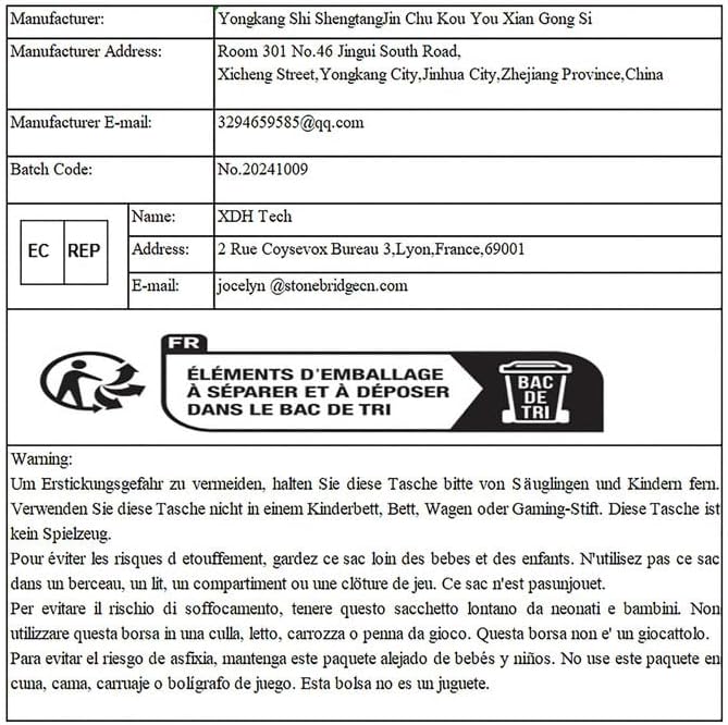
Image 7: Manufacturer contact information (for reference, actual contact methods may vary).
Manufacturer: GOOFIT (Yongkang Shi ShengtangJin Chu Kou You Xian Gong Si)
Model Number: H054-011
UPC: 702114877195