
1. Introduction
The Galaxy DX-959B is a high-performance mobile CB radio designed for reliable communication. It features both AM and Single Sideband (SSB) modes, a large, easy-to-read meter, and a comprehensive set of controls for optimal operation. This manual provides detailed instructions for the installation, operation, and maintenance of your DX-959B radio.
2. Important Safety Information
Please read and understand all safety instructions before operating the radio. Failure to do so may result in injury or damage to the equipment.
- Ensure the radio is connected to a 12-volt DC power source with correct polarity.
- Install the antenna properly to prevent damage to the radio and ensure optimal performance.
- Do not operate the radio while driving if it distracts you from safe vehicle operation.
- Avoid exposing the radio to extreme temperatures, moisture, or direct sunlight.
- Do not attempt to open or modify the radio. Refer all servicing to qualified personnel.
3. Package Contents
Verify that all items are present in the package:
- Galaxy DX-959B Mobile CB Radio
- Handheld Microphone
- Radio Mounting Bracket and Microphone Mounting Hardware
- Power Cord
- Owner's Manual (this document)
4. Product Overview
4.1 Front Panel Controls and Indicators
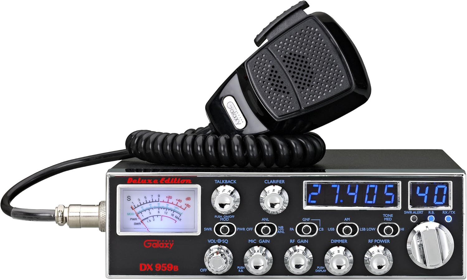
Figure 1: Front view of the Galaxy DX-959B Mobile CB Radio, showing the main display, controls, and connected microphone.
The front panel of the DX-959B provides access to all operational controls and indicators:
| Control/Indicator | Function |
|---|---|
| Meter | Displays Signal Strength (S-Meter up to 60 dB over S9), Modulation Percentage (for AM), Power Output (calibrated for AM and SSB), and SWR (Standing Wave Ratio). |
| Frequency Counter | Five-digit blue LED display showing the operating frequency. |
| Channel Display | Two-digit blue LED display showing the selected channel number. |
| SWR Control | Adjusts the SWR meter for accurate readings. Features an Automatic SWR Circuit and High SWR Alert LED. |
| TALKBACK | Adjusts the volume of your own voice heard through the speaker during transmission. Has an On/Off switch. |
| CLARIFIER | Fine-tunes the receive frequency for clearer SSB reception. |
| PWR OFF / MOD Switch | Toggles between Power Off and Modulation modes. |
| ANL / NB / PA Switch | Selects Automatic Noise Limiter (ANL), Noise Blanker (NB), or Public Address (PA) mode. |
| GNF / CB / USB / LSB Switch | Selects Galaxy Noise Filter (GNF), Citizen Band (CB), Upper Sideband (USB), or Lower Sideband (LSB) operation. |
| TONE MED / HI Switch | 3-position switch to adjust the receive audio tone. |
| SWR ALERT LED | Illuminates when SWR is excessively high. |
| R.B. (Roger Beep) LED | Indicates Roger Beep function is active. |
| RX/TX LED | Blue indicates Receive (RX), Red indicates Transmit (TX). |
| VOL-SQ (Volume/Squelch) | Inner knob controls audio volume; outer ring controls squelch level to suppress background noise. |
| MIC GAIN | Adjusts the microphone input sensitivity. |
| RF GAIN | Adjusts the sensitivity of the receiver to incoming signals. |
| DIMMER | Adjusts the brightness of the meter lamp and display LEDs. Push switch to turn off all illumination. |
| RF POWER | Adjusts the radio's output power. |
4.2 Rear Panel Connections
- Antenna Connector: Standard SO-239 connector for external antenna.
- External Speaker Jack: For connecting an optional external speaker.
- PA Speaker Jack: For connecting an external speaker for Public Address (PA) function.
- DC Power Input: For connecting the supplied 12V DC power cord.
5. Setup and Installation
5.1 Mounting the Radio
- Choose a secure and convenient location in your vehicle that does not obstruct driving or airbag deployment.
- Use the provided mounting bracket as a template to mark drilling locations.
- Drill pilot holes and secure the mounting bracket using the supplied hardware.
- Slide the radio into the bracket and secure it with the thumb screws.
5.2 Power Connection
- Connect the red wire of the power cord to the positive (+) terminal of your vehicle's 12V DC electrical system.
- Connect the black wire of the power cord to the negative (-) terminal or a good chassis ground point.
- Ensure connections are secure and properly insulated to prevent short circuits.
- Plug the power cord into the DC Power Input jack on the rear of the radio.
5.3 Antenna Connection
- Connect a properly tuned CB antenna (not included) to the Antenna Connector on the rear of the radio.
- It is crucial to ensure your antenna has a low Standing Wave Ratio (SWR) for optimal performance and to prevent damage to the radio's output stage. Consult an antenna specialist if unsure.
5.4 Microphone Connection
- Plug the microphone connector into the microphone jack located on the side of the radio.
- Secure the microphone using the provided mounting hardware in a convenient location.
6. Operating Instructions
6.1 Basic Operation
- Power On: Turn the VOL-SQ knob clockwise to power on the radio. The display and meter lamp will illuminate.
- Volume Adjustment: Adjust the inner VOL knob to a comfortable listening level.
- Squelch Adjustment: Rotate the outer SQ ring clockwise until background noise disappears. Rotate counter-clockwise to hear weaker signals.
- Channel Selection: Use the Channel Selector knob to choose your desired channel (1-40). The frequency display will show the corresponding frequency.
- Transmit: Press and hold the PTT (Push-To-Talk) button on the microphone to transmit. The RX/TX LED will turn red. Release to receive.
6.2 Advanced Features
- Mode Selection (GNF/CB/USB/LSB): Use the GNF/CB/USB/LSB switch to select your desired operating mode. CB is for standard AM operation. USB and LSB are for Single Sideband communication. GNF (Galaxy Noise Filter) helps reduce noise on weak SSB signals.
- Noise Reduction (ANL/NB): The ANL/NB/PA switch allows you to activate the Automatic Noise Limiter (ANL) for general noise reduction or the Noise Blanker (NB) for impulse noise like ignition interference.
- Public Address (PA): Select PA mode on the ANL/NB/PA switch to use the radio as a public address system through an external PA speaker.
- Clarifier: When operating in SSB mode, use the CLARIFIER knob to fine-tune the incoming signal for clear voice reproduction.
- Talkback: Adjust the TALKBACK knob to monitor your own voice through the radio's speaker during transmission.
- RF Gain: Use the RF GAIN knob to reduce receiver sensitivity for strong local signals, preventing overload and distortion.
- Mic Gain: Adjust the MIC GAIN knob to optimize your microphone's sensitivity for clear outgoing audio.
- RF Power: The RF POWER knob allows you to adjust the radio's output power.
- Dimmer: Rotate the DIMMER knob to adjust the brightness of the display and meter lamp. Push the knob to turn off all illumination.
- Roger Beep: The Roger Beep function, when activated, transmits a short tone at the end of your transmission, signaling to other operators that you have finished speaking.
7. Maintenance
- Cleaning: Use a soft, dry cloth to clean the radio's exterior. Do not use abrasive cleaners or solvents.
- Inspection: Periodically check all connections (power, antenna, microphone) for security and signs of wear.
- Antenna Tuning: Regularly check your antenna's SWR to ensure optimal performance and prevent radio damage.
8. Troubleshooting
| Problem | Possible Cause | Solution |
|---|---|---|
| No power/display | Loose power connection, blown fuse, incorrect wiring. | Check power cord, vehicle fuse, and wiring polarity. |
| No receive audio | Volume too low, squelch set too high, antenna disconnected. | Increase volume, decrease squelch, check antenna connection. |
| Poor transmit audio | Mic Gain too low, faulty microphone. | Adjust Mic Gain, test with another microphone if available. |
| High SWR reading | Poor antenna tuning, damaged antenna or cable, improper ground. | Inspect antenna and cable, check ground, re-tune antenna. |
| SSB signals unclear | Clarifier not adjusted, incorrect mode selected. | Adjust CLARIFIER knob, ensure USB or LSB mode is selected. |
9. Technical Specifications
| Feature | Specification |
|---|---|
| Brand | Galaxy |
| Model Number | DX959B |
| Number of Channels | 40 |
| Frequency Range | 26.965 MHz - 27.405 MHz |
| Voltage | 12 Volts DC |
| Item Weight | 4.4 pounds |
| Product Dimensions (H x W x D) | 2.5" x 9.5" x 8" (Depth does not include knobs or antenna connector) |
| Special Features | Roger Beep, Automatic SWR Circuit, High SWR Alert, Talkback, Variable Dimmer, Galaxy Noise Filter (GNF) |
| Water Resistance Level | Not Water Resistant |
10. Warranty Information
The Galaxy DX-959B Mobile CB Radio is covered by a Two Year Limited Warranty from the date of purchase. This warranty covers defects in materials and workmanship under normal use. Please retain your proof of purchase for warranty claims.
For detailed warranty terms and conditions, please refer to the official user manual PDF available at: Official User Manual (PDF)
11. Customer Support
If you encounter issues not covered in the troubleshooting section or require further assistance, please contact Galaxy customer support. Refer to the official product website or your purchase documentation for contact details.