1. Introduction
This manual provides comprehensive instructions for the safe and effective installation, operation, and maintenance of the ATS Diesel Performance 2029302272 Turbocharger System. This system is designed to enhance the performance of compatible diesel engines by increasing air intake, leading to improved power and efficiency. Please read this manual thoroughly before proceeding with any installation or operation.
2. Safety Information
Working with automotive components, especially engine systems, requires adherence to strict safety protocols. Failure to follow these guidelines may result in serious injury or damage to the vehicle.
- Always wear appropriate personal protective equipment, including safety glasses, gloves, and hearing protection.
- Ensure the vehicle is securely supported on jack stands or a lift before working underneath it.
- Disconnect the vehicle's battery before beginning any electrical work.
- Allow the engine and exhaust components to cool completely before handling to prevent burns.
- Turbochargers operate at high temperatures and speeds. Exercise extreme caution.
- It is highly recommended that installation be performed by a qualified automotive technician.
- Refer to the vehicle manufacturer's service manual for specific torque specifications and procedures.
3. Package Contents
Verify that all components listed below are present and undamaged before beginning installation. Contact ATS Diesel Performance immediately if any parts are missing or damaged.

Figure 3.1: Overview of the ATS Diesel Performance Turbocharger System components. This image displays the main turbocharger unit along with various installation hardware, including gaskets, bolts, and fluid lines, essential for a complete installation.
- ATS Diesel Performance Turbocharger Unit
- Mounting Gaskets and Seals
- Mounting Hardware (bolts, studs, nuts)
- Oil Feed and Drain Lines (if applicable to system)
- Coolant Lines (if applicable to system)
- Associated Connectors and Fittings
4. Setup and Installation
The installation of a turbocharger system is complex and requires specialized tools and knowledge. Professional installation is strongly recommended. The following steps are general guidelines and may vary depending on the specific vehicle application.
- Preparation:
- Ensure the engine is cool and the battery is disconnected.
- Drain engine oil and coolant if necessary for access.
- Remove any components obstructing access to the existing turbocharger or exhaust manifold.
- Removal of Existing Components:
- Carefully disconnect and remove the existing turbocharger, exhaust manifold, and associated plumbing.
- Clean all mating surfaces thoroughly to ensure proper sealing with new gaskets.
- Turbocharger Installation:

Figure 4.1: Front view of the ATS Diesel Performance turbocharger, highlighting the compressor housing and inlet. This component is responsible for drawing in and compressing ambient air before it enters the engine.
- Mount the new turbocharger to the exhaust manifold using the provided gaskets and hardware. Ensure proper alignment and torque all fasteners to vehicle manufacturer specifications.
- Connect the oil feed line to the turbocharger's oil inlet and the oil drain line to the engine block/oil pan. Ensure these lines are free of kinks and obstructions.
- If applicable, connect coolant lines to the turbocharger for cooling.
- Air Intake and Exhaust Connections:
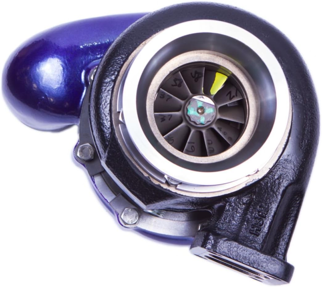
Figure 4.2: Close-up view of the turbocharger's compressor wheel. This wheel spins at high RPMs to draw in and compress air, which is then directed into the engine's intake manifold.
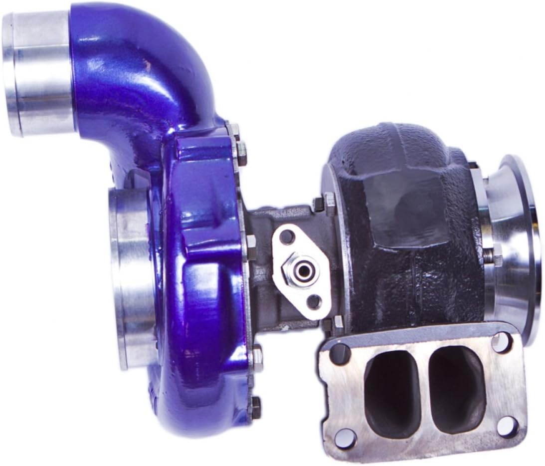
Figure 4.3: Side view of the ATS Diesel Performance turbocharger, showing the exhaust housing and flange. Exhaust gases from the engine drive the turbine wheel within this housing.
- Connect the air intake piping to the turbocharger inlet.
- Connect the charge air piping from the turbocharger outlet to the intercooler (if equipped) and then to the engine's intake manifold.
- Connect the exhaust downpipe to the turbocharger outlet.
- Final Checks:

Figure 4.4: Another side view of the turbocharger, illustrating the connection points for oil and coolant lines, and potentially a wastegate actuator. Proper connection of these lines is crucial for turbocharger longevity.
- Double-check all connections for tightness and proper routing.
- Refill engine oil and coolant to appropriate levels.
- Reconnect the battery.
- Start the engine and check for leaks, unusual noises, or warning lights.
- Perform a test drive, monitoring boost pressure and engine performance.
5. Operating Principles
A turbocharger utilizes the exhaust gases from the engine to spin a turbine wheel. This turbine is connected by a shaft to a compressor wheel. As the turbine spins, the compressor wheel also spins, drawing in ambient air and compressing it before forcing it into the engine's combustion chambers. This process, known as forced induction, allows the engine to burn more fuel and air, resulting in increased power output and improved efficiency compared to naturally aspirated engines of similar displacement.
6. Maintenance
Proper maintenance is crucial for the longevity and optimal performance of your ATS Diesel Performance Turbocharger System.
- Oil Quality: Ensure the engine oil is always at the correct level and changed according to the vehicle manufacturer's recommendations. Turbochargers rely heavily on clean, high-quality oil for lubrication and cooling.
- Oil Lines: Periodically inspect oil feed and drain lines for leaks, kinks, or blockages. Restricted oil flow can lead to premature turbocharger failure.
- Air Filters: Maintain a clean engine air filter. A dirty filter can restrict airflow, causing the turbocharger to work harder and potentially drawing in contaminants.
- Boost Leaks: Regularly check all charge air piping and connections for leaks. Boost leaks can reduce performance and increase exhaust gas temperatures.
- Cool-Down Period: After periods of high engine load, allow the engine to idle for a few minutes before shutting it off. This allows the turbocharger to cool down and prevents oil coking in the bearing housing.
7. Troubleshooting
This section outlines common issues and general troubleshooting steps. For detailed diagnostics, consult a qualified technician.
| Symptom | Possible Cause | Action |
|---|---|---|
| Loss of Engine Power / Low Boost | Boost leak, restricted air intake, faulty wastegate, turbocharger damage. | Inspect charge air pipes for leaks. Check air filter. Verify wastegate operation. Inspect turbocharger for damage. |
| Excessive Smoke (Blue/Black/White) | Oil leak into exhaust/intake, fuel system issues, turbocharger seal failure. | Check oil levels. Inspect turbocharger seals. Consult a mechanic for fuel system diagnosis. |
| Unusual Noises (Whining, Grinding) | Bearing wear, foreign object ingestion, impeller contact with housing. | Immediately shut off engine. Inspect turbocharger for damage. Professional inspection required. |
8. Specifications
- Brand: ATS Diesel Performance
- Model Number: 2029302272
- Manufacturer: ATS Diesel
- Product Type: Turbocharger System
- Compatibility: Refer to ATS Diesel Performance product catalog or contact support for specific vehicle applications.
9. Warranty and Support
For information regarding product warranty, technical support, or replacement parts, please contact ATS Diesel Performance directly through their official website or customer service channels. Keep your purchase receipt and product model number (2029302272) readily available when contacting support.
ATS Diesel Performance Official Website: www.atsdiesel.com


