
1. Introduction
This manual provides essential instructions for the setup, operation, and maintenance of your Turnigy 9X 9-Channel Transmitter, RF9X-V2 Module, and 9X8C-V2 8-Channel Receiver system. This system features v2 firmware, offering enhanced functionality and reliability for various remote-controlled models, including helicopters, airplanes (acro), and gliders. Please read this manual thoroughly before using the product to ensure safe and correct operation.
2. Safety Precautions
- Always operate your RC model in open areas, away from people, vehicles, and obstacles.
- Ensure all batteries are fully charged and properly installed before each use.
- Never operate your RC model near power lines, busy roads, or residential areas.
- Perform a range check before each flight to confirm proper signal reception.
- Keep the transmitter and receiver away from moisture and extreme temperatures.
- If a "SWITCH ERROR" message appears upon power-on, ensure all switches are in their correct (usually upward or neutral) positions before proceeding. This is a safety feature, not a fault.
3. Product Overview
The Turnigy 9X system is a 2.4GHz radio control system designed for hobbyists. It includes a 9-channel transmitter, an RF9X-V2 module, and a 9X8C-V2 8-channel receiver. The v2 firmware provides improved menu navigation and mixing capabilities.
3.1 Included Components
- Turnigy 9X 9-Channel Transmitter (Mode 2)
- Turnigy RF9X-V2 2.4GHz RF Module
- Turnigy 9X8C-V2 8-Channel Receiver
3.2 Transmitter Features
- Channels: 8ch PPM / 9ch PCM
- Display: 128*64 LCD
- Support Type: Helicopter (Heli), Aerobatic (Acro), Glider (Glid)
- User Memory: 8 models
- Stick Model: 4 (Mode 2 is default)
- Encoder Type: PPM/PCM
- Subtrim: Yes
- Simulator Interface: Yes
- Buzzer: Yes
- Low Voltage Show: Yes
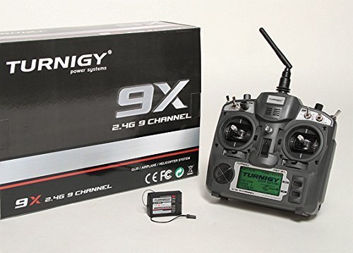
Figure 1: Turnigy 9X 9-Channel Transmitter. This image shows the front view of the transmitter, highlighting the LCD screen, control sticks, and various switches.
4. Setup
4.1 Battery Installation
The Turnigy 9X Transmitter requires a battery for operation (not included). Typically, 8 AA batteries or a compatible LiFe/LiPo battery pack are used. Open the battery compartment cover on the back of the transmitter. Insert the batteries, ensuring correct polarity. If using a battery pack, connect it to the designated connector. Close the cover securely. Ensure the battery contacts are clean and secure to prevent intermittent power issues.
4.2 Binding Transmitter and Receiver
To establish communication between the transmitter and receiver, a binding process is required. Follow these general steps:
- Ensure the transmitter is OFF and all switches are in their neutral or upward positions.
- Connect the bind plug to the BIND/BAT port on the 9X8C-V2 receiver.
- Power on the receiver (e.g., by connecting a speed controller with BEC or a separate receiver battery). The receiver's LED should flash rapidly.
- While holding down the bind button on the RF9X-V2 module (located on the back of the transmitter), power on the transmitter.
- The receiver's LED should stop flashing and remain solid, indicating successful binding.
- Release the bind button on the transmitter, then power off both the transmitter and receiver.
- Remove the bind plug from the receiver.
- Power on the transmitter first, then the receiver. The receiver's LED should illuminate solid, confirming the link.
Note: If the receiver LED continues to flash, repeat the binding process.
4.3 Initial Model Configuration
Upon first use or when setting up a new model, you will need to configure the model type (Heli, Acro, Glid) and other basic settings through the transmitter's menu. Refer to the "Operating" section for menu navigation instructions.
"SWITCH ERROR" Message: If you power on the transmitter and see a "SWITCH ERROR" message on the LCD, it means one or more of the physical switches on the transmitter are not in their default (usually upward or neutral) position. Move all switches to their correct positions, then power cycle the transmitter. This is a safety feature to prevent unintended model operation.
5. Operating the Transmitter
5.1 Powering On/Off
To power on the transmitter, ensure all switches are in their default positions, then slide the power switch to the ON position. To power off, slide the power switch to the OFF position. Always power on the transmitter before the model and power off the model before the transmitter.
5.2 Basic Controls (Mode 2)
- Left Stick (Throttle/Rudder): Vertical movement controls throttle (up/down). Horizontal movement controls rudder (left/right).
- Right Stick (Aileron/Elevator): Vertical movement controls elevator (up/down). Horizontal movement controls aileron (left/right).
- Trims: Small levers adjacent to the sticks for fine-tuning control surfaces.
- Switches: Various 2-position and 3-position switches for functions like gear, flaps, flight modes, etc.
5.3 Menu Navigation
The 128x64 LCD screen and surrounding buttons are used to navigate the transmitter's settings. Use the UP/DOWN buttons to scroll through options, the MENU button to enter sub-menus or confirm selections, and the EXIT button to go back or cancel.
Key menu items include:
- MODEL SELECT: Choose from up to 8 stored model configurations.
- MODEL TYPE: Set the model as Helicopter, Aerobatic, or Glider.
- SYSTEM SETTINGS: Adjust general transmitter settings.
- FUNCTION SETTINGS: Configure specific model functions like subtrim, endpoints, mixes, etc.
5.4 Subtrim Adjustment
Subtrim allows for fine adjustment of servo neutral positions without affecting the main trim levers. Access the Subtrim setting within the FUNCTION SETTINGS menu. Adjust values incrementally to achieve perfectly centered control surfaces.
5.5 Simulator Interface
The transmitter includes a simulator interface port, typically a 3.5mm jack. This allows you to connect the transmitter to a computer using a compatible simulator cable (sold separately) for practice with flight simulator software. Ensure the transmitter is powered on and the simulator software is configured correctly to recognize the input.
6. Maintenance
6.1 Cleaning
Wipe the transmitter's exterior with a soft, dry cloth. Avoid using harsh chemicals or solvents, which can damage the plastic and electronic components. Keep the LCD screen clean and free from dust and fingerprints.
6.2 Storage
Store the transmitter in a cool, dry place, away from direct sunlight and extreme temperatures. If storing for an extended period, remove the batteries to prevent leakage and corrosion. It is recommended to store the transmitter in a protective case to prevent physical damage.
6.3 Battery Care
Regularly inspect battery contacts for corrosion. If using rechargeable batteries, follow the manufacturer's charging instructions. Do not overcharge or over-discharge batteries. Dispose of old or damaged batteries responsibly according to local regulations.
7. Troubleshooting
| Problem | Possible Cause | Solution |
|---|---|---|
| "SWITCH ERROR" message on startup. | One or more switches are not in their default position. | Ensure all switches are in their neutral or upward positions, then power cycle the transmitter. |
| Receiver LED flashes rapidly, not solid. | Transmitter and receiver are not bound, or binding failed. | Repeat the binding procedure as described in Section 4.2. Ensure the bind plug is correctly inserted and the transmitter's bind button is held during power-on. |
| No response from model/servos. |
|
|
| Intermittent control or short range. |
|
|
8. Specifications
| Feature | Detail |
|---|---|
| Number of Channels | 8ch PPM / 9ch PCM |
| Display | 128*64 LCD |
| Support Type | Heli / Acro / Glid |
| User Memory | 8 models |
| Stick Model | 4 (Mode 2 default) |
| Encoder Type | PPM / PCM |
| Subtrim | Yes |
| Simulator Interface | Yes |
| Buzzer | Yes |
| Low Voltage Show | Yes |
| Package Dimensions | 14.8 x 10.5 x 5 inches |
| Item Weight | 2.1 pounds |
| ASIN | B00URCJQ9M |
| Item Model Number | 9x |
| Manufacturer Recommended Age | 6 years and up |
| Manufacturer | HobbyKing |
9. Warranty and Support
For warranty information and technical support, please contact HobbyKing directly through their official website or customer service channels. Keep your purchase receipt as proof of purchase for any warranty claims.


