1. Introduction
The SkyRC Brushless Motor Analyzer is a precision tool designed for comprehensive analysis of brushless motors used in RC applications. It provides detailed insights into motor performance by measuring key parameters such as KV value, RPM, current draw, and motor timing. This manual provides instructions for the proper setup, operation, and maintenance of your analyzer.

Figure 1: SkyRC Brushless Motor Analyzer with key components and dimensions. The device measures approximately 136.5mm in length, 80.6mm in width, and 24.5mm in height. It features a Hall Effect Sensor LED, Throttle Level LED Indicators, a Rotary Dial, and an LCD display. Motor power wires (C, B, A) and a sensor connector are located on the front panel.
2. Package Contents
Verify that all items listed below are present in your package. If any items are missing or damaged, please contact your retailer.

Figure 2: Contents of the SkyRC Brushless Motor Analyzer package. Includes the main Motor Analyzer unit, a Motor Sensor Cable, three Motor Cables (A, B, C), DC Input Power Cables with Banana Connector, DC Input Power Cables with Tamiya Connector, and an Instruction Manual.
- SkyRC Brushless Motor Analyzer Unit
- Motor Sensor Cable
- 3x Motor Cables (A, B, C)
- DC Input Power Cable with Banana Connector
- DC Input Power Cable with Tamiya Connector
- Instruction Manual
3. Setup and Connections
Follow these steps to properly connect your brushless motor to the analyzer. Ensure all connections are secure before powering on the device.
3.1. Brushless Motor with Sensor
- Connect the motor sensor cable from the motor to the "SENSOR CONNECTOR" port on the analyzer.
- Connect the three motor power wires (A, B, C) from the motor to the corresponding "MOTOR POWER WIRES A, B, C" ports on the analyzer.
- Connect a 2-cell LiPo battery (or other compatible DC power source) to the power input port of the analyzer. Caution: Reverse polarity will damage this unit.
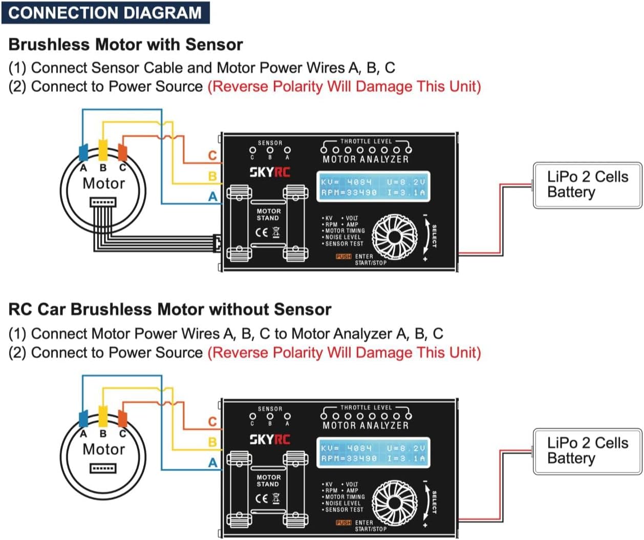
Figure 3: Connection diagram for a brushless motor with a sensor. The sensor cable connects to the analyzer's sensor port, and the three motor phase wires (A, B, C) connect to their respective ports. A 2-cell LiPo battery provides power to the analyzer.
3.2. Brushless Motor without Sensor
- Connect the three motor power wires (A, B, C) from the motor to the corresponding "MOTOR POWER WIRES A, B, C" ports on the analyzer. The sensor connector will remain unused.
- Connect a 2-cell LiPo battery (or other compatible DC power source) to the power input port of the analyzer. Caution: Reverse polarity will damage this unit.
Figure 4: Connection diagram for a brushless motor without a sensor. Only the three motor phase wires (A, B, C) connect to their respective ports on the analyzer. A 2-cell LiPo battery provides power.
4. Operation
The SkyRC Brushless Motor Analyzer allows for various measurements to assess motor performance. Use the rotary dial to navigate menus and adjust settings, and the "PUSH ENTER START/STOP" button to confirm selections or start/stop tests.
4.1. Basic Measurements (KV, RPM, Voltage, Current)
After connecting the motor and power source, the analyzer will display real-time data on the 2x16 character LCD.
- KV Value: RPM per Volt, indicating the motor's speed constant.
- RPM: Revolutions Per Minute, the rotational speed of the motor.
- Voltage (U): The input voltage supplied to the motor.
- Current (I): The current drawn by the motor.

Figure 5: The analyzer displaying KV, RPM, Voltage (U), and Current (I) values. The motor is placed on the stand for testing.
4.2. Motor Timing Analysis
The analyzer can measure the physical endbell timing of the motor, typically ranging from 0 to 70 degrees. This requires tools to rotate the sensor board for adjustment.
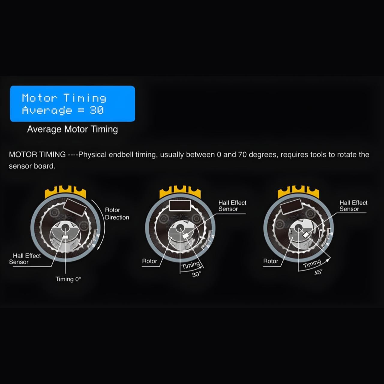
Figure 6: Illustration of motor timing. The diagram shows how rotating the sensor board changes the timing relative to the rotor, from 0 degrees to 30 degrees and 45 degrees. The analyzer displays the average motor timing.
4.3. Hall Effect Sensor Check and Timing
For sensored brushless motors, the analyzer can perform a comprehensive test of the Hall Effect sensors and display the actual timing of each sensor element (Phase A, B, and C).
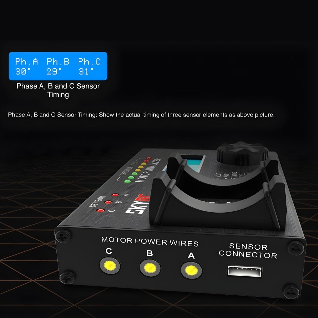
Figure 7: The analyzer displaying individual timing for Phase A, Phase B, and Phase C sensors. This provides critical information for optimizing sensored motor performance.
4.4. Noise Level Detection
The analyzer can detect noise levels from 60dB to 120dB. This feature helps assess motor health and identify potential issues such as worn bearings or rotor imbalance.
5. Maintenance
- Cleaning: Use a soft, dry cloth to clean the analyzer. Do not use solvents or abrasive cleaners.
- Storage: Store the analyzer in a dry, cool place away from direct sunlight and extreme temperatures.
- Cable Care: Inspect all cables regularly for signs of wear or damage. Replace damaged cables immediately to prevent malfunction or injury.
6. Troubleshooting
- No Power: Ensure the power source is correctly connected and fully charged. Check for correct polarity.
- Incorrect Readings: Verify all motor and sensor connections are secure. Ensure the motor is properly seated on the stand.
- "Reverse Polarity" Warning: Immediately disconnect the power source. Recheck the polarity of your power connection. Connecting with reverse polarity will cause permanent damage to the unit.
- Display Issues: If the LCD is not displaying correctly, try restarting the unit. If the problem persists, contact support.
7. Specifications
| Feature | Specification |
|---|---|
| Item Model Number | SK-500020 |
| Package Dimensions | 6.61 x 5.04 x 2.2 inches |
| Item Weight | 9.9 ounces |
| Manufacturer | SKYRC |
| Display | 2x16 Character LCD |
| Timing Range | 0 to 70 degrees |
| Noise Level Detection | 60dB to 120dB |
8. Warranty and Support
For warranty information and technical support, please refer to the official SkyRC website or contact your local distributor. Keep your purchase receipt as proof of purchase for warranty claims.
Note: Product specifications and appearance are subject to change without prior notice.


