1. Introduction
Thank you for choosing the Avidsen 107104 Digital Multimeter. This compact, handheld device is designed for measuring various electrical parameters, including DC voltage, AC voltage, DC current, and resistance. It features a 3.5-digit digital display for clear readings and double insulation for enhanced safety. Please read this manual thoroughly before use to ensure proper operation and to prevent potential hazards.
2. Safety Information
Always observe the following safety precautions when using the multimeter:
- Double Insulation: The multimeter features double insulation for user protection. Do not attempt to bypass or modify this safety feature.
- Measurement Categories: This device is rated CAT III 300V and CAT II 500V. Ensure that the measurement category and voltage rating are appropriate for the circuit being tested.
- Inspect Test Leads: Before each use, inspect the test leads for any damage to the insulation or exposed metal. Do not use damaged leads.
- Do Not Exceed Maximum Input Values: Refer to the specifications section for maximum input values for each function. Exceeding these limits can damage the meter and pose a safety risk.
- Fuse Protection: The multimeter is protected by fuses (500mA 500V Fastrapid and 10A 500V Fastrapid). If a fuse blows, replace it only with a fuse of the specified type and rating.
- Battery Level: Ensure batteries are adequately charged. A low battery indicator may affect measurement accuracy.
- Environmental Conditions: Operate the multimeter within the specified operating temperature range (0°C to +40°C).
- Proper Connection: Always connect the common (COM) test lead first, then the live test lead. Disconnect the live test lead first, then the common test lead.
- Avoid Wet Conditions: Do not use the multimeter in wet or damp environments.
3. Product Overview
The Avidsen 107104 Digital Multimeter features a clear digital display, a rotary function switch, and input jacks for test leads.

Figure 1: Front view of the Avidsen 107104 Digital Multimeter, showing the display, rotary switch, and input terminals.
Key Components:
- Digital Display: 3.5-digit LCD for displaying measurement values, with automatic polarity indication. Maximum display: 1999.
- Rotary Function Switch: Used to select the desired measurement function and range (e.g., DCV, ACV, DCA, Resistance, Diode, Continuity).
- Input Jacks:
- COM (Common) Jack: For the black (negative) test lead.
- VΩmA Jack: For the red (positive) test lead when measuring voltage, resistance, or current up to 200mA.
- 10A Jack: For the red (positive) test lead when measuring current up to 10A. Note: Maximum 10 seconds every 10 minutes for 10A measurements.
- Test Probes: Two insulated test probes (red and black) are included for making connections to the circuit under test.
4. Setup
4.1 Battery Installation
The Avidsen 107104 Multimeter operates on two 3V AAA batteries (included). To install or replace batteries:
- Ensure the multimeter is turned OFF.
- Locate the battery compartment cover on the back of the unit.
- Use a screwdriver to remove the screw securing the battery compartment cover.
- Carefully remove the cover.
- Insert two 3V AAA batteries, observing the correct polarity (+ and -) as indicated inside the compartment.
- Replace the battery compartment cover and secure it with the screw.
Note: An accumulator level indicator is present to show battery status. Replace batteries when the indicator shows low power to maintain measurement accuracy.
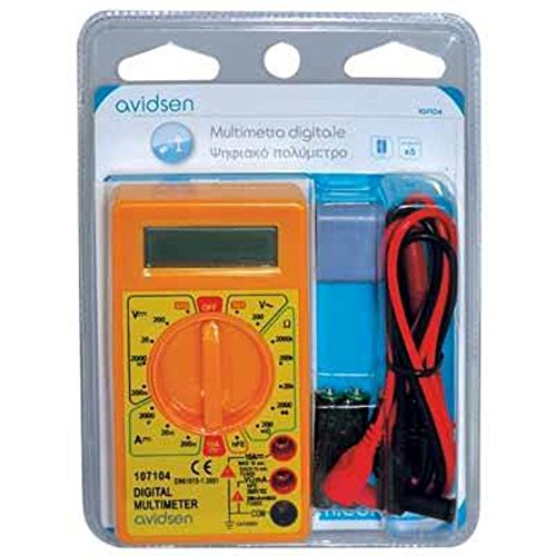
Figure 2: Avidsen 107104 Digital Multimeter shown in its retail packaging, which includes the multimeter, test leads, and batteries.
5. Operating Instructions
Before taking any measurements, ensure the test leads are securely plugged into the correct input jacks.
5.1 Measuring DC Voltage (V=)
- Insert the red test lead into the VΩmA jack and the black test lead into the COM jack.
- Set the rotary switch to the desired DCV range (e.g., 200m, 2000m, 20, 200, 500). If the voltage is unknown, start with the highest range and decrease as needed.
- Connect the test probes across the component or circuit to be measured.
- Read the voltage value on the digital display.
5.2 Measuring AC Voltage (V~)
- Insert the red test lead into the VΩmA jack and the black test lead into the COM jack.
- Set the rotary switch to the desired ACV range (e.g., 200, 500). If the voltage is unknown, start with the highest range.
- Connect the test probes across the AC voltage source.
- Read the voltage value on the digital display.
5.3 Measuring DC Current (A=)
- For currents up to 200mA: Insert the red test lead into the VΩmA jack and the black test lead into the COM jack.
- For currents up to 10A: Insert the red test lead into the 10A jack and the black test lead into the COM jack. Caution: Do not measure more than 10 seconds every 10 minutes when using the 10A range.
- Set the rotary switch to the desired DCA range (e.g., 2000µ, 20m, 200m, 10A).
- Turn off the power to the circuit. Open the circuit where the current is to be measured.
- Connect the multimeter in series with the circuit.
- Turn on the power to the circuit.
- Read the current value on the digital display.
- Turn off the power, disconnect the multimeter, and restore the circuit.
5.4 Measuring Resistance (Ω)
- Insert the red test lead into the VΩmA jack and the black test lead into the COM jack.
- Set the rotary switch to the desired Resistance range (e.g., 200, 2000, 20k, 200k, 2000k).
- Ensure the circuit or component to be measured is de-energized.
- Connect the test probes across the component.
- Read the resistance value on the digital display.
5.5 Diode Test ( )
)
- Insert the red test lead into the VΩmA jack and the black test lead into the COM jack.
- Set the rotary switch to the Diode test position.
- Connect the red probe to the anode and the black probe to the cathode of the diode. A forward voltage drop (typically 0.5V to 0.8V for silicon diodes) will be displayed.
- Reverse the probes. The display should show "OL" (Open Loop) for a good diode.
5.6 Continuity Test ()
- Insert the red test lead into the VΩmA jack and the black test lead into the COM jack.
- Set the rotary switch to the Continuity test position.
- Connect the test probes across the component or circuit.
- If the resistance is below a certain threshold (typically around 50Ω), the multimeter will emit an audible beep, indicating continuity. The display will also show the resistance value.
6. Maintenance
6.1 Cleaning
Wipe the case with a damp cloth and mild detergent. Do not use abrasives or solvents. Ensure the multimeter is completely dry before use.
6.2 Battery Replacement
Refer to section 4.1 for battery replacement instructions. Replace batteries promptly when the low battery indicator appears to ensure accurate readings.
6.3 Fuse Replacement
If the multimeter fails to measure current, the fuse may be blown. To replace a fuse:
- Ensure the multimeter is turned OFF and test leads are disconnected.
- Remove the battery compartment cover (refer to 4.1).
- Carefully locate the fuse(s) inside the compartment.
- Gently remove the blown fuse.
- Replace it only with a fuse of the exact specified type and rating:
- For VΩmA input: 500mA 500V Fastrapid (FØ 5 x 20 mm)
- For 10A input: 10A 500V Fastrapid (FØ 5 x 20 mm)
- Replace the battery compartment cover and secure it.
7. Troubleshooting
| Problem | Possible Cause | Solution |
|---|---|---|
| No display or faint display | Dead or low batteries | Replace batteries (see Section 4.1) |
| "OL" (Overload) displayed | Input value exceeds selected range or meter's maximum capacity | Select a higher range or ensure input is within meter's limits. |
| Incorrect or unstable readings | Low battery, poor test lead connection, incorrect range selection, external interference | Replace batteries, check connections, select appropriate range, move away from strong electromagnetic fields. |
| Cannot measure current | Blown fuse, incorrect test lead connection (e.g., using VΩmA jack for 10A measurement) | Check and replace fuse (see Section 6.3), ensure test lead is in the correct current jack (VΩmA or 10A). |
8. Specifications
- Display: 3.5-digit LCD, Max. 1999, with automatic polarity indication.
- Measurement Rate: 2-3 updates per second.
- Power Source: 2 x 3V AAA batteries (included).
- Fuses:
- 500mA 500V Fastrapid (for VΩmA input)
- 10A 500V Fastrapid (for 10A input)
- Double Insulation: Yes.
- Safety Rating: CAT III 300V, CAT II 500V.
- Operating Temperature: 0°C to +40°C.
- Storage Temperature: -10°C to +50°C.
- Dimensions: 126 mm x 70 mm x 27 mm.
- Weight: Approximately 210g (with batteries).
- Functions: DC Voltage, AC Voltage, DC Current, Resistance, Diode Test, Continuity Test.
9. Warranty and Support
Avidsen products are manufactured to high-quality standards. For warranty information or technical support, please refer to the warranty card included with your product or visit the official Avidsen website. Keep your purchase receipt as proof of purchase.


