1. Important Safety Information
Read and understand all safety warnings and instructions before operating this welding machine. Failure to follow these instructions may result in electric shock, fire, serious injury, or death.
- Electric Shock Can Kill: Do not touch live electrical parts. Wear dry welding gloves and protective clothing. Insulate yourself from the work and ground.
- Fumes and Gases Can Be Hazardous: Keep your head out of the fumes. Use ventilation or exhaust to remove fumes from the breathing zone.
- Arc Rays Can Burn Eyes and Skin: Wear a welding helmet with a proper shade filter. Wear protective clothing to protect skin.
- Fire and Explosion Hazard: Remove all flammable materials from the welding area. Have a fire extinguisher nearby.
- Hot Parts Can Cause Severe Burns: Allow welded materials to cool before handling.
- Magnetic Fields: Pacemaker wearers should consult their doctor before operating.
- Falling Objects: Secure workpieces before welding.
- Noise: Wear hearing protection.
Always ensure proper grounding and use appropriate personal protective equipment (PPE) including welding helmet, gloves, and protective clothing.
2. Product Overview
The XtremepowerUS MIG-195 is a gas-less flux core wire welding machine designed for welding normal thin steel and iron. It features automatic wire feed and operates on 220V power. This compact welder is suitable for home DIY projects and general repair work.

Figure 1: XtremepowerUS MIG-195 Gas-Less Flux Core Welder with included welding mask, ground clamp, and torch.
3. Setup Instructions
3.1 Unpacking and Inspection
- Carefully remove all components from the packaging.
- Inspect the welder and all accessories for any signs of damage during shipping. If any damage is found, do not operate the machine and contact customer support.
- Ensure all included components are present: MIG 195 Welder, Torch, Ground Cord, Chipping Hammer/Wire Brush, Tip, Welding Mask.
3.2 Power Connection
This welder requires a 220V power supply. Ensure your electrical outlet matches this requirement. The unit comes with a power plug that may require wiring to a suitable 220V receptacle. Consult a qualified electrician if unsure about wiring.

Figure 2: Included power plug components. This welder operates on 220V. Consult a qualified electrician if unsure about wiring.
3.3 Wire Spool Installation
The MIG-195 is designed for gas-less flux core welding. Use appropriate flux core wire for your application.
- Open the side panel of the welder to access the wire feed mechanism.
- Place the wire spool onto the spool holder. Ensure the wire unwinds smoothly from the bottom of the spool towards the wire feed rollers.
- Thread the wire through the guide tube and into the wire feed rollers.
- Close the wire feed roller tension arm and adjust the tension. The tension should be firm enough to feed the wire without slipping, but not so tight that it deforms the wire.
- Feed the wire through the torch liner until it exits the contact tip. You may need to press the trigger on the welding torch to activate the wire feed motor.

Figure 3: Internal view of the welder, illustrating the wire feed mechanism and spool holder for flux core wire.

Figure 4: A spool of flux core welding wire, suitable for use with the MIG-195 welder.
3.4 Polarity Setting
For gas-less flux core welding, the polarity is typically DC electrode negative (DCEN), meaning the welding torch is connected to the negative terminal (-) and the ground clamp to the positive terminal (+). Verify the correct polarity for your specific flux core wire type.
3.5 Ground Clamp Connection
Connect the ground clamp to the workpiece. Ensure a clean, bare metal connection for optimal electrical conductivity. A poor ground connection can lead to unstable arcs and poor weld quality.

Figure 5: The welding torch and ground clamp, essential components for the welding process.
4. Operating Instructions
4.1 Controls Overview
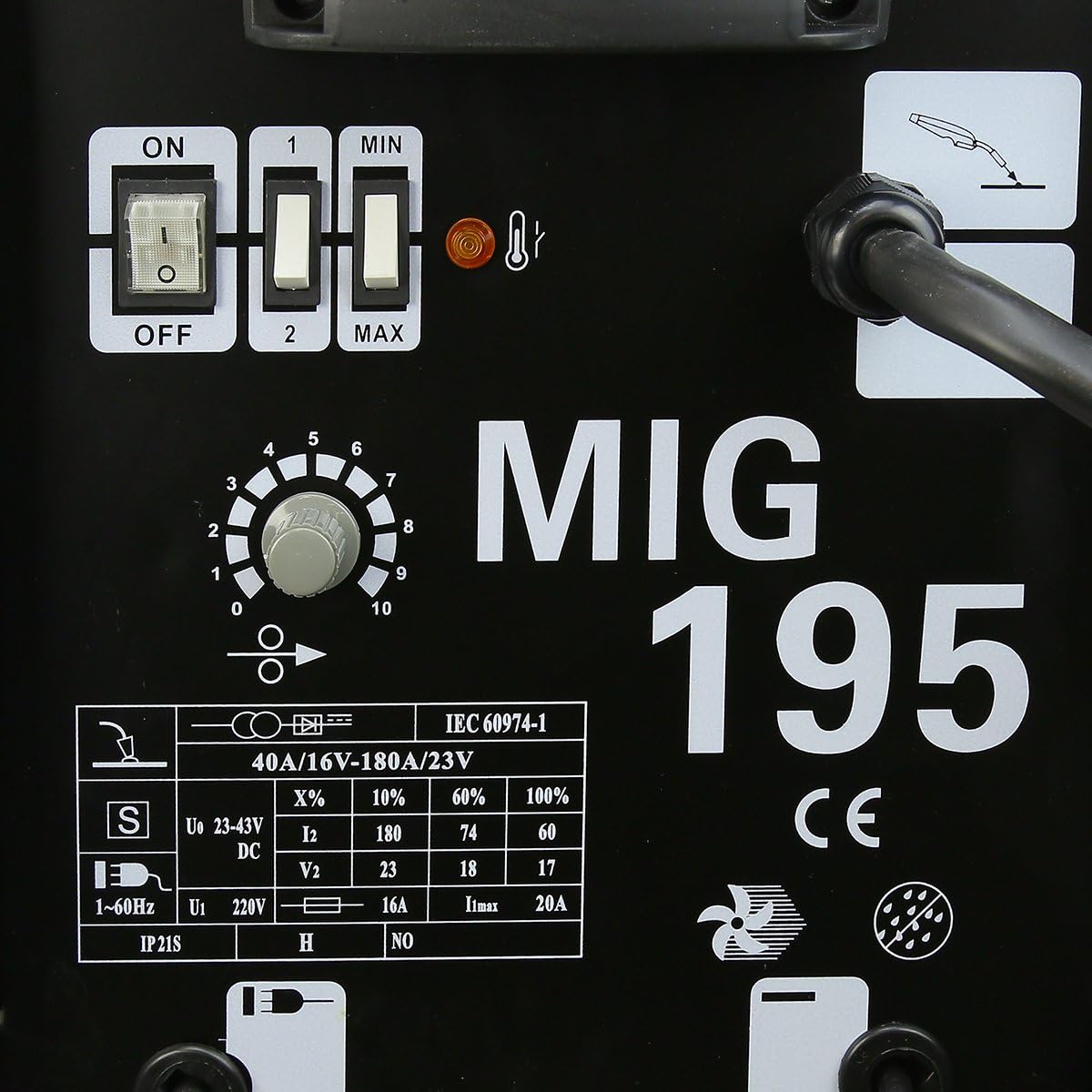
Figure 6: Detailed view of the control panel, showing power switches, voltage/amperage selectors, and wire feed speed dial.
- ON/OFF Switch: Powers the unit on or off.
- Voltage/Amperage Selector (1/2, MIN/MAX): Adjusts the welding power output. Use '1' for lower power and '2' for higher power. Within each setting, 'MIN' and 'MAX' provide fine-tuning.
- Wire Feed Speed Dial (0-10): Controls the speed at which the welding wire is fed through the torch. Higher numbers indicate faster wire feed.
- Thermal Overload Indicator: A light that illuminates if the machine overheats, indicating the need for a cool-down period.
4.2 Welding Process
- Prepare Workpiece: Ensure the workpiece is clean, free of rust, paint, and grease.
- Set Parameters: Refer to the welding setup guide (often located inside the welder's cover) or a welding chart for recommended voltage and wire feed speed settings based on material thickness and wire diameter.
- Wear PPE: Always wear your welding helmet, gloves, and protective clothing.
- Start Welding: Position the torch tip approximately 1/4 to 3/8 inch from the workpiece. Press the trigger to start the wire feed and initiate the arc.
- Maintain Arc: Move the torch steadily along the joint, maintaining a consistent arc length and travel speed. Observe the weld puddle and adjust your technique as needed.
- Finish Weld: Release the trigger to stop the arc and wire feed. Allow the weld to cool before chipping away the slag (from flux core).
4.3 Duty Cycle
The duty cycle indicates how long a welding machine can operate continuously within a 10-minute period before needing to cool down. Exceeding the duty cycle can damage the machine.
- 10% at 180 AMP
- 60% at 74 AMP
- 100% at 60 AMP
For example, at 180 AMP, the machine can weld for 1 minute out of every 10 minutes. If the thermal overload indicator lights up, stop welding and allow the machine to cool down.
4.4 Wire Capacity
- Flux Core: 0.047" (1.2mm), 0.023" to 0.035" (0.6-0.8mm)
- Steel & Stainless Steel (Solid Wire, requires gas): 0.031" (0.8mm)
- Aluminum (Solid Wire, requires gas): 0.030" to 0.039" (1.0mm)
Note: This model is primarily advertised as "Gas-Less" for flux core welding. Using solid wire for steel or aluminum would require an external gas supply and regulator, which are not included with this specific "Gas-Less" model.
5. Maintenance
Regular maintenance ensures the longevity and safe operation of your welding machine.
- Clean Regularly: Use compressed air to blow out dust and debris from the machine's vents and internal components. Do this periodically, especially in dusty environments.
- Inspect Cables and Connections: Check all cables (power, ground, torch) for cuts, fraying, or loose connections. Replace damaged cables immediately.
- Torch Maintenance:
- Clean the contact tip and nozzle regularly to remove spatter.
- Replace worn contact tips and nozzles as needed.
- Ensure the torch liner is free of kinks and blockages for smooth wire feeding.
- Wire Feed Mechanism: Keep the wire feed rollers clean. Check for proper tension and alignment.
- Ground Clamp: Ensure the ground clamp is clean and makes good contact with the workpiece.

Figure 7: Common spare parts for the welder, such as fuses, contact tips, washers, and circlips, which may require periodic replacement.
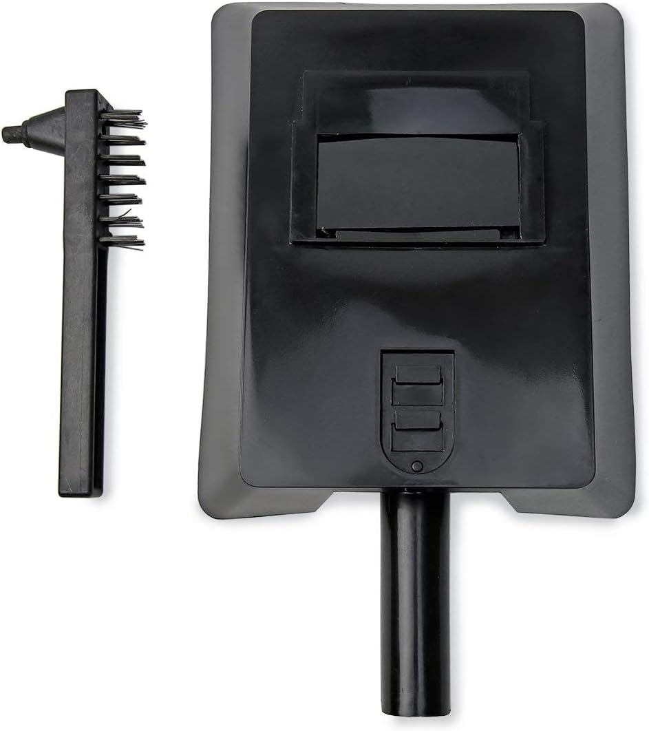
Figure 8: Included welding mask and chipping hammer with wire brush, useful for post-weld cleaning and protection.
6. Troubleshooting
This section addresses common issues you might encounter during operation.
| Problem | Possible Cause | Solution |
|---|---|---|
| No power to the machine | Power switch off, circuit breaker tripped, loose power connection. | Ensure power switch is ON. Check circuit breaker. Verify power cord is securely plugged in. |
| No arc when trigger is pulled | Poor ground connection, incorrect polarity, wire not feeding, contact tip blocked, machine in thermal overload. | Clean and secure ground clamp. Check polarity. Ensure wire feeds smoothly. Clean or replace contact tip. Allow machine to cool if thermal light is on. |
| Wire not feeding smoothly | Wire spool tangled, wire feed tension incorrect, torch liner blocked or kinked, wrong size contact tip. | Untangle wire spool. Adjust wire feed tension. Inspect and clear torch liner. Use correct contact tip for wire diameter. |
| Poor weld quality (porosity, weak welds) | Improper settings (voltage/wire speed), dirty workpiece, incorrect travel speed, wrong wire type. | Adjust voltage and wire feed speed according to material. Clean workpiece thoroughly. Practice consistent travel speed. Ensure flux core wire is suitable. |
| Machine overheats (thermal light on) | Exceeded duty cycle, insufficient ventilation. | Stop welding and allow the machine to cool down. Ensure adequate airflow around the machine. Reduce welding time or amperage. |
7. Specifications
| Feature | Detail |
|---|---|
| Model | MIG-195 |
| Part Number | 55016 |
| Brand | XtremepowerUS |
| Power Source | Corded-Electric |
| Voltage | 220 Volts |
| Welding Current | 60-190 AMP (MIN) |
| Duty Cycle (10 min period) | 10% at 180AMP, 60% at 74 AMP, 100% at 60 AMP |
| Wire Capacity (Flux Core) | 0.047" (1.2mm), 0.023" to 0.035" (0.6-0.8mm) |
| Wire Capacity (Solid Wire) | 0.031" (0.8mm) steel & stainless steel, 0.030" to 0.039" (1.0mm) aluminum (requires external gas) |
| Item Weight | 30 pounds (approx. 13.6 kg) |
| Product Dimensions | 27 x 17 x 18 inches (approx. 68.6 x 43.2 x 45.7 cm) |
| Material | Metal, Steel, Aluminum |
| Included Components | MIG 195 Welder, Torch, Ground Cord, Chipping Hammer/Wire Brush, Tip, Welding Mask |
8. Warranty and Support
For warranty information, technical support, or to order replacement parts, please contact XtremepowerUS customer service. Refer to the contact information provided with your product packaging or visit the official XtremepowerUS website.
When contacting support, please have your model number (MIG-195) and part number (55016) available.


