1. Introduction and Overview
The Autonics ENC-1-1-T-24 is an incremental wheel type rotary encoder designed for precise measurement of length or speed of continuously moving objects. This encoder provides an output waveform proportional to the measured distance, calibrated to international measurement units (meters or inches). It operates on a 12-24VDC power supply and features a totem pole output.
This manual provides essential information for the safe and effective installation, operation, and maintenance of your ENC-1-1-T-24 encoder.
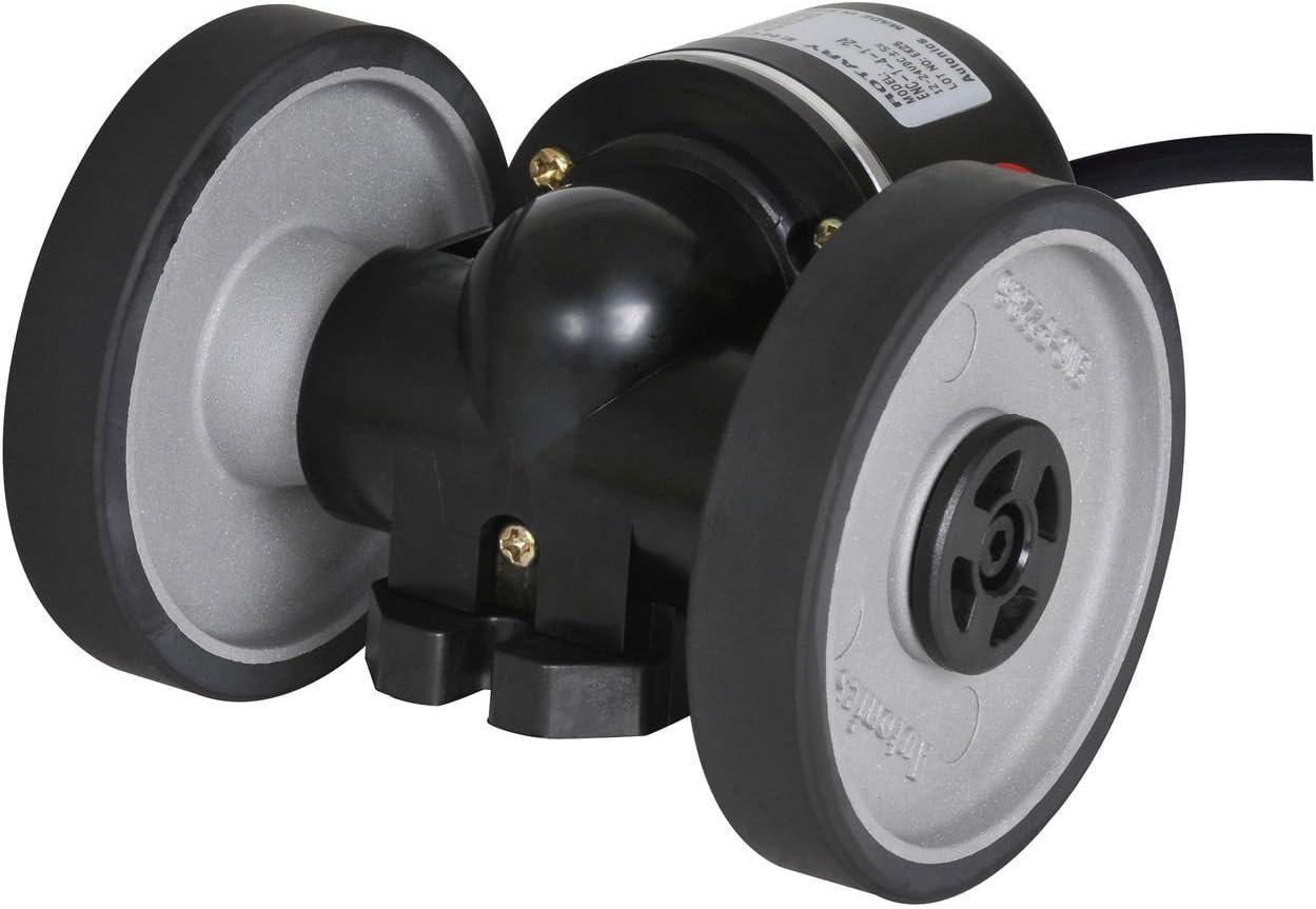
Figure 1: Autonics ENC-1-1-T-24 Incremental Wheel Type Encoder. This image shows the black encoder unit with two grey wheels attached, designed for surface contact measurement. The wheels have black rubberized treads for grip.
2. Safety Information
Please read and understand all safety precautions before installing or operating the device. Failure to follow these instructions may result in injury or damage to the product.
- Ensure the power supply is disconnected before performing any wiring or maintenance.
- Verify the power supply voltage is within the specified range (12-24VDC ±5%).
- Do not disassemble or modify the product. Unauthorized modifications may lead to malfunction or safety hazards.
- Install the device in an environment free from excessive vibration, dust, moisture, and corrosive gases.
- Ground the product properly to prevent electrical shock and ensure stable operation.
3. Product Features
The ENC-1-1-T-24 encoder offers several key features:
- Wheel Type Design: Ideal for measuring length or speed of continuously moving objects by direct contact.
- High Resolution: Provides 1 pulse per 1mm of movement, ensuring precise measurement.
- Totem Pole Output: Offers a robust output signal suitable for various industrial control systems.
- Wide Voltage Range: Operates reliably with a 12-24VDC ±5% power supply.
- Versatile Application: Suitable for use in packaging machinery, rolling machinery, textile machinery, and other industrial automation systems.
4. Package Contents
Upon opening the package, please verify that all components are present and undamaged:
- Autonics ENC-1-1-T-24 Incremental Wheel Type Encoder Unit
- User Manual (this document)
- Mounting accessories (if applicable, check packaging for specifics)
If any items are missing or damaged, please contact your supplier immediately.
5. Setup and Installation
5.1 Mounting
Mount the encoder securely to a stable surface, ensuring that the wheels make firm and consistent contact with the object to be measured. The mounting position should allow for proper alignment and prevent slippage during operation. Consider the direction of movement and the desired measurement axis when positioning the encoder.
5.2 Wiring
The ENC-1-1-T-24 features a totem pole output. Refer to the following general wiring guidelines. Always consult the specific wiring diagram provided with your unit for precise connections, as color codes may vary.
| Wire Color (Typical) | Function | Description |
|---|---|---|
| Brown | +V (Power Supply) | Connect to 12-24VDC power source. |
| Blue | 0V (Ground) | Connect to common ground. |
| Black | Output A | Phase A signal output. |
| White | Output B | Phase B signal output (90° phase shift from A). |
| Orange | Output Z (Index) | Reference pulse output (one pulse per revolution). |
Important: Ensure all connections are secure and insulated to prevent short circuits. Incorrect wiring can damage the encoder or connected equipment.
6. Operating Instructions
Once properly installed and wired, the ENC-1-1-T-24 encoder will generate pulse signals corresponding to the movement of the object it is measuring. These pulses can be fed into a counter, PLC, or other control system to determine length, speed, or position.
- Direction Detection: The phase difference between Output A and Output B allows for detection of the direction of rotation or movement.
- Pulse per Millimeter: The encoder generates 1 pulse for every 1mm of linear movement of the measured surface.
- Speed Measurement: By counting pulses over a specific time interval, the speed of the object can be calculated.
- Length Measurement: By accumulating the total number of pulses, the total length of the object can be determined.
Refer to the documentation of your connected control system (e.g., PLC, counter) for specific programming and configuration details to interpret the encoder's output signals.
7. Maintenance
The Autonics ENC-1-1-T-24 encoder is designed for reliable operation with minimal maintenance. However, periodic checks can help ensure its longevity and accuracy.
- Cleaning: Regularly clean the encoder wheels and the surface they contact to prevent accumulation of dust, debris, or oil, which can affect measurement accuracy. Use a soft, dry cloth. Do not use harsh chemicals or abrasive materials.
- Inspection: Periodically inspect the mounting for tightness and ensure the wheels are making proper contact with the measured surface. Check the cable for any signs of wear or damage.
- Environment: Ensure the operating environment remains within the specified conditions (temperature, humidity, vibration).
8. Troubleshooting
If you encounter issues with your ENC-1-1-T-24 encoder, refer to the following common troubleshooting steps:
| Problem | Possible Cause | Solution |
|---|---|---|
| No output signal | No power or incorrect wiring. | Check power supply connections (+V and 0V). Verify wiring against the diagram. |
| Inaccurate measurement | Slippage of wheels, debris on wheels/surface, or incorrect mounting pressure. | Ensure firm contact between wheels and surface. Clean wheels and surface. Adjust mounting pressure if possible. |
| Intermittent signal | Loose connections, damaged cable, or electrical noise. | Check all wiring connections for tightness. Inspect cable for damage. Consider shielding or grounding improvements if electrical noise is suspected. |
| Incorrect direction detection | Output A and B signals are swapped or misinterpreted by the control system. | Verify A and B wiring. Check control system's configuration for quadrature decoding. |
If the problem persists after attempting these solutions, contact Autonics technical support or your local distributor for further assistance.
9. Specifications
Key technical specifications for the Autonics ENC-1-1-T-24 encoder:
- Model: ENC-1-1-T-24
- Type: Incremental Wheel Type Encoder
- Pulses Per Unit: 1 Pulse Per 1mm
- Output Type: Totem Pole Output
- Power Supply: 12-24VDC ±5%
- Material: Copper (internal components, as per product data)
- Dimensions: Approximately 1 x 1 x 1 inches (Product dimensions, refer to detailed drawings for exact measurements)
- Weight: Approximately 1.09 pounds
- Usage: Professional Industrial Applications
Note: Specifications are subject to change without prior notice for product improvement.
10. Warranty and Support
For warranty information, please refer to the warranty card included with your product or visit the official Autonics website. Autonics provides technical support and customer service to assist with any inquiries regarding product installation, operation, or troubleshooting.
Autonics Official Website: www.autonics.com
Please have your product model number (ENC-1-1-T-24) and serial number ready when contacting support.


